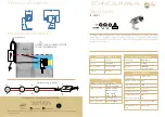
3.
Place the sand fill cover over
the tank opening to prevent the
sand from getting into the
standpipe
.
4. Fill the tank approximately 1/2
full of water.
5. Pour the recommended amount
of sand into the tank, making sure
that the standpipe remains
centered and vertical. Level the
surface upon completion.
6. Remove the sand-fill cover.
Sand Fill Cover Assembly
7. Preassemble the clamps with
one screw and one nut, turning
the screw 3-4 turns only.
8. Carefully remove all sand
particles from the valve mounting
surfaces.
9. Place the O-Ring onto the
bottom of the valve body.
10. Lower the dial valve carefully
into position so that its underside
engages with the standpipe.
Rotate the valve until the inlet is
approximately in line with the
pump.
11. Place clamps around tank
and valve neck and assemble
second screw and nut.
12. Firmly tap with a rubber mallet
outside of the clamps as you
tighten both screws alternately
and evenly.
13. Make sure screws are
tightened until clamps are
completely closed.
14. Install the pressure gauge
into the threaded opening in the
dial valve.
15. Install the backwash adapter,
Clamp
Screw
Clamp
Bolt
7 Position Dial Valve Installation
O-Ring
Clamps are
completely
closed
Clamp Installation
if necessary, to reduce backwash flow.
Install 2 threaded adapters into pump
discharge and dial valve inlet after
wrapping threads with 4 to 8 wraps of
Teflon tape. Place one hose clamp over
each end of pump to filter hose and
push hose on to each adapter. Position
clamps over barbed portion of adapter
and tighten.
You are now ready to connect the sys-
tem to your pool.
Dial Valve Inlet
Pump Discharge
PLUMBING CONNECTIONS
The provision of gate valves and unions in the pump suction and pool return lines
of a permanent installation will make servicing easier and prevent loss of water while
routine maintenance is in progress. Pump Installation: Follow the instructions
supplied with the pump. Connect the pipes to the filter system as shown on page 2.
Clamp
Do not use pipes smaller than the connections provided. Support the plumbing
so that it puts no strain on either the pump or the filter.
FOR SOLVENT WELD CONNECTIONS
Rigid or flexible PVC pipe can be used. Pipe ends should be clean and free of
any debris caused by the cutting operation. Be sure that the proper adhesive
is used on the type of pipe specified. Recommended Adhesives: These are
examples only and are not intended to restrict brands:
PVC-PVC Joint
PVC-ABS Joint
Uni-Weld Pool-Tite 2000
Uni-Weld Pool-Tite 2000
Suregard Flex 20
Suregard Weld-All No. 5
IPS Weld-On 705
IPS Weld-On 794
Note:
A primer will assure that adhesive joints are superior. Suregard P-3000
has a purple tracer to qualify in areas where codes specify a primer must be
used.
Caution:
We recommend that you consider climatic conditions when applying
adhesives. Certain atmospheric situations, such as high moisture content,
make the adhesive action of certain glues less effective. Check the
manufacturer’s instructions.
FOR THREADED CONNECTIONS
Use only Teflon tape or equivalent on threaded plumbing connections. Other
pipe compounds may damage threads. We do not recommend the use of
silicone or petroleum based compounds. DO NOT OVER-TIGHTEN: HAND-
TIGHTEN PLUS 1/2 TURN IS SUFFICIENT.
FILTER PLUMBING
If the filter is equipped with union connections, union adapters are needed to
complete plumbing connections and may need to be ordered separately.
You are now ready to fill your pool and begin system start-up procedures.
SYSTEM START-UP
For above-ground pools with sys-
tem below the pool water level:
1a. Press down on the valve handle
and rotate to the FILTER position
and release. Pool water will flow into
the filter tank, pump and strainer.
When water level reaches the clear
strainer cover on the pump, the fil-
ter is ready for operation.
NOTE:
If
an optional shut-off valve is in-
stalled, be sure that it is fully
opened.
For in-ground pools with system
above the pool water level:
1b. Unscrew the Ring-Lok nut on the
pump and remove the clear strainer
cover. Prime the pump by filling the
strainer with water to the bottom of
the inlet. Replace the clear cover and
Ring-Lok nut. HAND-TIGHTEN
ONLY.
Priming
Level
OR
3. A) Set dial valve to DRAIN posi-
tion.
B) Start pump.
C) After flow has been established,
stop pump.
D) Set valve to BACKWASH posi-
tion.
When it has been determined that
the pump motor is operating prop-
erly, stop the pump and proceed to
Step 3.
Backwash
Standard
3-prong
plug
Refer to information on motor nameplate for electri-
cal service data. If the pump on your system is sup-
plied with a 3-prong twist lock 115V plug, then the
appropriate female receptacle should be installed.
Connect only to a grounding type receptacle pro-
tected by a Ground Fault Circuit Interrupter
(GFCI).
Motors should have fused disconnect switch
or circuit breaker and wire size large enough for pump
horsepower and distance from power source. Wiring
should be done in accordance with applicable codes
by a competent electrician.
3-prong
twist-lock plug
ELECTRICAL DATA
CAUTION
!
Wire Length
HP 50 ft. 100 ft.
3/4 #14G #12G
1 #12G #10G
To guard against
low voltage which can damage pump motor,
use minimum wire gauge.
Do not operate your pump until it has been
filled with water (primed).
CAUTION
!
2. Turn the motor on (for only a few
seconds) by plugging the unit into the
Grounded electrical receptacle.
DO NOT USE AN
EXTENSION CORD.
WARNING
WARNING
WARNING
WARNING
WARNING
!
3


