6 ADJUSTMENTS
16
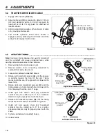
6.4
TRACTION DRIVE IDLER CABLE_____________________________________________
1. Engage OPC handle.
[ See 4.1]
2. Adjust cable nuts
(E)
as required to obtain 0.18 inch
(3.3 mm) deflection with a 4.4 lb (2.0 kg) push for
new belt or 3.0 lb (1.4 kg) push for used belt at
location shown.
3. Addition adjustment available at handle end of cable
or by moving cable bracket.
4. Test handle operation. When OPC handle is
engaged, parking brake
(F)
should release and idler
pulley should engage traction drive.
Figure 6C
6.5
AERATOR TIMING _________________________________________________________
Note:
Improper timing between the aerator crankshaft
and the camshaft will cause elongated holes while
aerating and excessive noise in the camcase.
1. Remove shields from both sides of unit.
2. Remove aerator chain connecting crankshaft to
camshaft from both sides of unit.
3. Loosen stud between crankshaft halves.
4. Rotate right camshaft sprocket
(G)
until the keyway
is pointing towards the front of the unit. Timing
marks should be at a 45° angle with dot towards the
lower front.
5. Rotate right side crankshaft sprocket
(H)
until the
timing marks are horizontal with the dot towards the
front. Keyway should be at a 45° angle.
6. Install right side aerator chain
(J)
. Crankshaft
sprocket may be rotated up to 5° in a clockwise
direction only to properly mesh with the chain.
7. Rotate left crankshaft sprocket
(K)
until the timing
marks are vertical and dot is towards the ground.
8. Install left side aerator chain
(L)
. Crankshaft
sprocket may be rotated up to 5° in a counter-
clockwise direction only to properly mesh with the
chain.
9. Tighten stud between crankshaft halves.
10. Install shields
Figure 6D
Figure 6E
E
F
0.18 inch (3.3 mm)
4.4 lb (1.81 kg) New
3.0 lb (1.36 kg) Used
Timing Marks
Horizontal
Timing Marks
45° Angle
Dot towards
lower front
Dot towards
front
Front
Right Side Aerator Chain
G
H
J
Left Side Aerator Chain
Front
Timing Marks
Vertical
Dot towards
ground
K
L
Содержание GA 24
Страница 27: ......
Страница 58: ...32 3 11 5 9 8 7 10 6 5 1 Ref 1 2 2 4 GA 24 3 1 Aerator Enclosure Serial No All...
Страница 62: ...36 8 7 7 7 5 5 4 4 2 6 6 3 3 1 22 10 9 13 12 14 11 15 16 17 18 19 20 21 GA 24 5 1 Chassis Serial No All...
Страница 78: ...52 2 1 1 3 2 1 4 5 6 9 3 8 7 8 10 11 12 13 14 13 15 GA 24 13 1 Slide and Glide Assmebly Serial No All...
Страница 80: ...54 1 2 3 4 5 10 12 6 11 11 8 9 7 13 13 14 GA 24 14 1 Turf Guard Assembly Serial No All...
Страница 86: ......
Страница 87: ......

