background image

AFINAÇÕES    3

11

3.8

ALTURA DE CORTE________________________________________________________

A altura de corte dos rolos pode ser ajustada de 19 a
133 mm em incrementos de 6 mm. A altura de corte poderá
variar ligeiramente das alturas dadas dependendo das
condições do solo e de outros factores.


1. Estacione o aparador de relva numa superfície plana e

nivelada e rebaixe completamente as unidades de
corte. Coloque blocos na armação do conjunto de corte
para que esteja apoiada por todos os lados.

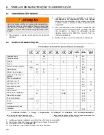
2. Consulte o gráfico fornecido para saber a altura

desejada de corte.

3.

Para rebaixar a altura de corte

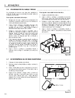
, retire os três pinos

de fixação 

(A)

. Eleve ligeiramente a manga exterior do

eixo 

(B) 

e retire os espaçadores de 13 mm 

(D) 

e/ou o

espaçador de 6 mm 

(E)

 de baixo, um de cada vez, até

ter obtido a altura de corte desejada. Retire
cuidadosamente os blocos e baixe as armações do
conjunto de corte 

(C)

. Coloque os espaçadores

restantes acima do eixo e insira os pinos de fixação. A
anilha 

(F)

 fica sempre por cima, imediatamente abaixo

do pino de fixação.

4.

Para aumentar a altura de corte

, retire os três pinos

de fixação 

(A)

. Eleve cuidadosamente a armação do

conjunto de corte 

(C) 

acima da altura de corte

desejada e apoie-a com calços. Acrescente
espaçadores de 13 mm 

(D)

 e/ou um espaçador de 6

mm 

(E)

,


conforme desejado, até obter a altura de corte

pretendida. Baixe a armação do conjunto de corte.
Coloque os espaçadores restantes acima do eixo e
insira os pinos de fixação. A anilha 

(F)

 fica sempre por

cima, imediatamente abaixo do pino de fixação.

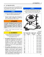
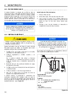
Figura 3G

AVISO

Ao cortar áreas onduladas, uma altura de corte baixa 

poderá causar desrelvamentos. Ajuste adequa-damente 

a altura de corte para evitar danos ao solo.


ATENÇÃO

Para evitar lesões graves, baixe o conjunto de corte até
que esteja completamente assente nos carretos
dianteiros e no rolo traseiro. Isto evitará um
rebaixamento acidental ao fazer os ajustes. Desengrene
toda a transmissão, accione o travão de
estacionamento, pare o motor e retire a chave da
ignição.


CUIDADO

 Use as técnicas devidas de elevação  ao elevar ou 

rebaixar as armações do conjunto de corte. As 

armações do conjunto de corte pesam 

aproximadamente 23 kg.

!

!

AVISO

Para uma melhor qualidade de corte, coloque sempre 

o mesmo número de espaçadores debaixo da 

armação do conjunto de corte nos três eixos. Ajuste 

todos os conjuntos de corte à mesma altura.

Altura  

corte 
(mm)

Espaç. 13 mm 
abaixo armaç. 

cortador

Espaç. 13 mm 
abaixo armaç. 

cortador

Posição do 

espaçador de

6 mm

19 

0

9

Acima armação

25

0

9

Abaixo armação

31

1

8

Acima armação

37

1

8

Abaixo armação

43

2

7

Acima armação

50

2

7

Abaixo armação

56

3

6

Acima armação

62

3

6

Abaixo armação

68

4

5

Acima armação

75

4

5

Abaixo armação

81

5

4

Acima armação

87

5

4

Abaixo armação

93

6

3

Acima armação

100

6

3

Abaixo armação

106

7

2

Acima armação

112

7

2

Abaixo armação

118

8

1

Acima armação

125

8

1

Abaixo armação

133

9

0

Acima armação

E

F

D

B

A

C

D

Содержание AR-522 jossa ROPS

Страница 1: ...correcta avisada sobre os perigos que ela pode causar e deve ler todo o manual antes de tentar preparar conduzir afinar ou reparar a m quina WARNING If incorrectly used this machine can cause severe...

Страница 2: ...e harm FOREWORD Suggested Stocking Guide To keep your equipment fully operational and productive Jacobsen suggests you maintain a stock of the more commonly used maintenance items We have included par...

Страница 3: ...4 3 Engine Oil 14 4 4 Air Filter 15 4 5 Fuel 15 4 6 Fuel System 15 4 7 Battery 16 4 8 Jump Starting 16 4 9 Charging Battery 16 4 10 Muffler and Exhaust 17 4 11 Hydraulic Hoses 17 4 12 Hydraulic Oil 17...

Страница 4: ...elds discharge deflectors or other protective devices securely fastened in place 12 Never disconnect or bypass any switch 13 Do not change the engine governor setting or overspeed the engine 14 Carbon...

Страница 5: ...nance should always be performed by a qualified technician If additional information or service is needed contact your Authorized Jacobsen Dealer who is kept informed of the latest methods to service...

Страница 6: ...aldson dry type with evacuator valve and service indicator Alternator 40 Amp 2 3 MOWER _________________________________________________________________ Tires Front 26 5 x 14 12 6 ply Rear 22 5 x 10 8...

Страница 7: ...ttachments Air Blow Gun JAC5098 Orange Touch up Paint 12 oz spray 554598 2 Post ROPS with Seat Belt 67844 Canopy Sunshade 68095 Hood Locking Latch 1004049 Cruise Control 67846 Wheel Kit 68090 High Lif...

Страница 8: ...Tighten nut to hold adjustment in place Figure 3A 3 3 BELT____________________________________________________________________ Inspect and adjust new belt after first ten hours of operation Adjust ev...

Страница 9: ...r from rolling Adjust nut C as required Figure 3C 3 5 NEUTRAL ADJUSTMENT ___________________________________________________ Neutral adjustment can only be made at the drive pump The Neutral adjustmen...

Страница 10: ...Start engine and check forward speed Repeat procedure until 10 mph 16 kph forward transport speed is attained To adjust reverse speed 1 Set forward speed 2 Start engine and check reverse travel speed...

Страница 11: ...rs on top of spindle and insert snap lock pins Washer F is always on top under snap lock pin Figure 3G NOTICE When cutting undulating areas lower cutting heights may cause scalping Adjust height accor...

Страница 12: ...ds Horn will beep when controller enters calibration mode 5 Tap the lift lever to raise position and wait for 3 to 5 seconds Repeat if required until cutting units just begin to raise 6 Tap the lift l...

Страница 13: ...Nm 75 8 4 100 11 3 107 12 1 143 16 1 9 16 18 ft lb Nm 92 124 122 165 129 174 172 233 1 4 28 in lb Nm 85 9 6 115 13 0 120 13 5 163 18 4 5 8 11 ft lb Nm 113 153 151 204 159 215 211 286 5 16 18 in lb Nm...

Страница 14: ...fe of the engine During the break in period Jacobsen recommends the following 1 During the first 50 hours of operation a new engine should be allowed to reach an operating temperature of at least 140...

Страница 15: ...e filler neck Use clean fresh 2 Diesel fuel minimum Cetane Rating 45 Refer to Engine Manual for additional information Check fuel lines and clamps every 50 hours Replace fuel lines and clamps at the f...

Страница 16: ...gative terminal on the good battery to the frame of mower with discharged battery After cables have been connected start the engine on the vehicle with the good battery then start the mower 4 9 CHARGI...

Страница 17: ...seated before tightening d Keep the hose from twisting Twisted hoses can cause couplers to loosen as the hose flexes during operation resulting in oil leaks e Kinked or twisted hoses can restrict the...

Страница 18: ...l individual wires away from moving parts to prevent damage 4 Make sure the seat switch harness is connected to the main wire harness 5 Check the battery and battery charging circuit 6 Do not wash or...

Страница 19: ...ware and any accessories within the ROPS should be inspected regularly and all damaged parts replaced immediately 2 Once the ROPS has been subjected to any form of impact it should be replaced 3 Check...

Страница 20: ...n cause a piece of the blade to break away and be hurled from the mower causing very serious injury to bystanders or property damage 3 A bent blade could have a microscopic crack G that can grow and a...

Страница 21: ...r or any other electrical components or at bearing housings and seals 4 Clean all plastic or rubber trim with a mild soap solution or use commercially available vinyl rubber cleaners 5 To maintain the...

Страница 22: ...1 While the engine is warm remove drain plug drain the oil from the crankcase and change oil filter Install drain plug and refill with fresh oil Torque drain plug to 22 ft lb 30 Nm 2 Clean exterior o...

Страница 23: ...or runs poorly 1 Fuel level low fuel or fuel filter dirty 1 Fill with fresh fuel Change fuel filter Bleed fuel lines 2 Air cleaner dirty 2 Inspect and replace air filter 3 Injectors fuel pump 3 Consu...

Страница 24: ...and Fuel Valve Hold Coil lamp 27 must be on NOTICE For factory assistance with troubleshooting controller problems please note the controller hardware revision and software version located on the lowe...

Страница 25: ...at not all switches are located on the instrument panel The traction pedal reel lift limit and brakes are controlled by small proximity switches mounted on the frame of the mower If an input lamp does...

Страница 26: ...l See 4 7 I Pack bearings with NLGI Grade 2 Service Class GB II Manual grease gun with NLGI Grade 2 Service Class LB III Engine Oil See Section 4 3 IV Jacobsen Hydraulic Oil SAE 10W30 or Greens Care 6...

Страница 27: ...4 4 5 5 5 5 5 5 5 5 5 5 6 7 8 8 9 9 10 10 12 12 12 11 Grease Fittings F1 50 Hours Every Week 1 Mower Pivot 5 2 Lift Arm Pivot 5 3 Lift Cylinders 10 4 Caster Pivot and Wheels 10 5 Mower Rear Roller 10...

Страница 28: ...the order 2 Explain where and how to make shipment 3 Give product number name and serial number that is stamped on the name plate or serial plate of your product 4 Order by the quantity desired the p...

Страница 29: ......

Страница 30: ...Inclu mos n meros de pe as para materiais adicionais de apoio e ajudas para treino Para encomendar qualquer do material seguinte 1 Escreva o seu nome e endere o completos na sua nota da encomenda 2 De...

Страница 31: ...r 14 4 4 Filtro de ar 15 4 5 Combust vel 15 4 6 Sistema de combust vel 15 4 7 Bateria 16 4 8 Arranque induzido 16 4 9 Carregar a bateria 16 4 10 Silenciador e escape 17 4 11 Mangueiras hidr ulicas 17...

Страница 32: ...seguramente montados no lugar 12 Nunca desligue interruptores nem fa a pontes 13 N o altere a afina o do regulador do motor nem acelere excessivamente 14 O mon xido de carbono dos gases de escape pode...

Страница 33: ...ou assist ncia adicional dever entrar em contacto com o seu vendedor autorizado de Jacobsen que est informado sobre os m todos de assist ncia mais recentes a este equipamento e pode prestar assist nc...

Страница 34: ...seco com v lvula evacuadora e indicador de assist ncia Alternador 40 Amp 2 3 APARADOR DE RELVA ____________________________________________________ Pneus Dianteiros 26 5 x 14 12 6 telas Traseiros 22...

Страница 35: ...a retoques aspersor em lata de 340 ml 554598 ROPS de 2 lugares com cinto de seguran a 67844 Capota 68095 Trinco de capot 1004049 Programador de velocidade 67846 Conjunto de rodas 68090 L mina subida a...

Страница 36: ...olte a apertar a porca para manter a afina o Figura 3A 3 3 CORREIA ________________________________________________________________ Verifique e regule uma correia nova ap s as primeiras dez horas de s...

Страница 37: ...parador de relva se movimente Aperte a porca C conforme necess rio Figura 3C 3 5 AFINA O NEUTRA _______________________________________________________ A afina o da posi o neutra s pode ser feita na b...

Страница 38: ...logo que o interruptor de igni o ligado 5 Ligue o motor e verifique a velocidade Repita o processo at se atingir a velocidade de avan o de 16 km h Para regular a velocidade da marcha atr s 1 Engate a...

Страница 39: ...a Baixe a arma o do conjunto de corte Coloque os espa adores restantes acima do eixo e insira os pinos de fixa o A anilha F fica sempre por cima imediatamente abaixo do pino de fixa o Figura 3G AVISO...

Страница 40: ...TCS durante 5 segundos A buzina apita quando o controlador entra no modo de calibragem 5 Levar a alavanca de subir para a posi o de subir e aguardar 3 a 5 segundos Se necess rio repetir at as unidade...

Страница 41: ...Nm 82 111 109 148 115 156 154 209 1 4 20 in lb Nm 75 8 4 100 11 3 107 12 1 143 16 1 9 16 18 ft lb Nm 92 124 122 165 129 174 172 233 1 4 28 in lb Nm 85 9 6 115 13 0 120 13 5 163 18 4 5 8 11 ft lb Nm 1...

Страница 42: ...omenda o seguinte 1 Durante as primeiras 50 horas de opera o deve se permitir que um motor novo atinja uma temperatura operacional de pelo menos 60 C antes de funcionar a toda carga 2 Verifique o n ve...

Страница 43: ...ma es adicionais Verifique as linhas de combust vel e as bra adeiras a intervalos de 50 horas Substitua linhas de combust vel e bra adeiras ao primeiro sinal de danos Armazene combust vel em conformid...

Страница 44: ...stado estrutura do aparador de relva que est com a bateria descarregada Depois de os cabos terem sido ligados arranque o motor no ve culo com a bateria em bom estado e em seguida arranque o aparador d...

Страница 45: ...de apertar d N o deixe as mangueiras ficarem torcidas Mangueiras torcidas podem provocar afrouxamento dos acoplamentos quando a mangueira flexionar durante a opera o resultando em vazamentos de leo e...

Страница 46: ...ido entre em contacto com o distribuidor autorizado da Jacobsen 3 Mantenha todos os fios individuais afastados de pe as m veis para evitar danos 4 Certifique se de que o interruptor da base est ligado...

Страница 47: ...ontagem dos equi pamentos e de quaisquer acess rios no interior do sistema ROPS devem ser inspeccionados periodica mente fazendo se a substitui o imediata de todos os componentes danificados 2 Depois...

Страница 48: ...a separa o e projec o de um estilha o de l mina do cortador o que poder originar les es muito graves a qualquer pessoa ou material que esteja nas proxim idades 3 Uma l mina dobrada poder ter uma fissu...

Страница 49: ...e veda es dos mancais 4 Limpe todo o acabamento de pl stico ou borracha com uma solu o fraca de sab o ou utilize detergentes para vinil borracha dispon veis em estabelecimentos comerciais 5 Para mante...

Страница 50: ...renagem drene o leo do c rter e troque o filtro de leo Instale o tamp o de drenagem e encha com leo novo Aperte o buj o de drenagem com um bin rio de 30 Nm 2 Limpe a parte externa do motor Pinte parte...

Страница 51: ...1 Encha com combust vel fresco Substitua o filtro de com bust vel Purgue a tubagem de combust vel 2 Depurador do ar sujo 2 Verifique e substitua o filtro de ar 3 Injectores bomba de combust vel 3 Con...

Страница 52: ...el l mpada 27 t m de estar ligados AVISO Para obter assist ncia de f brica na resolu o de problemas com o controlador anote a o n mero de revis o do controlador e a vers o de software localizados no c...

Страница 53: ...terruptores se encontram localizados no painel de instrumentos O pedal de trac o o fim de curso da desloca o do rolo e os trav es s o comandados por pequenos interruptores de l mina montados no quadro...

Страница 54: ...tr lito Ver 4 7 I Lubrifique mancais e rolamentos com NLGI Grau 2 Classe de servi o GB II Pistola de lubrifica o manual com NLGI Grau 2 Classe de servi o LB III leo para o motor veja a Sec o 4 3 IV le...

Страница 55: ...8 9 9 10 10 12 12 12 11 Pontos de lubrifica o F1 50 Horas Semanalmente 1 Eixo do cortador 5 2 Articula o do bra o elevador 5 3 Cilindros de eleva o 10 4 Eixo e folga das rodas 10 5 Rolo traseiro 10 6...

Страница 56: ...do produto o nome e o n mero de s rie que se encontram gravados na chapa de caracter sticas ou na chapa de s rie do seu produto 4 Encomende a quantidade desejada da pe a sobressalente referindo o c d...

Страница 57: ...ulics 61 19 1 Hydraulic Valves and Filter 62 20 1 Deck Hydraulics 63 21 1 Traction Hydraulics 64 22 1 Front Lift Hydraulics 66 23 1 Rear Lift Hydraulics 67 24 1 Wheel Motor Case Drains 68 25 1 Deck Mo...

Страница 58: ...tting Units Lower 6 Slowly depress traction pedal READ MANUAL BEFORE OPERATING REPLACEMENT MANUAL AVAILABLE FROM JACOBSEN TEXTRON CHARLOTTE NC 4124445 WARNING 1 Read operators manual Do not allow untr...

Страница 59: ...acid To avoid injury when jumping battery 1 Connect positive terminal to positive terminal 2 Connect negative terminal on good battery to frame of vehicle that has dead battery DANGER 3001435 105dB LW...

Страница 60: ...32 1 2 17 22 5 4 7 9 3 18 15 17 20 22 16 19 10 10 23 24 16 11 14 12 8 16 15 21 6 AR 522 2 1 Hood Serial No All LF34 1...

Страница 61: ...Module 10 800794 4 Screw 5 16 18 x 3 4 Hex Flange 11 400408 2 Screw 1 2 13 x 1 1 2 Hex Head 12 444758 2 Locknut 1 2 13 Center 13 800907 4 Nut 5 16 18 Hex Flange 14 453017 2 Flat Washer 1 2 15 366883 1...

Страница 62: ...34 10 3 19 5 6 9 4 30 16 24 25 2 6 9 8 22 23 18 6 9 10 1 20 21 12 7 14 15 13 11 26 27 17 8 28 29 31 33 34 37 38 39 35 36 32 32 40 41 42 42 42 AR 522 3 1 Seat Pan Michigan Seat Serial No All...

Страница 63: ...20 445245 2 Tinnerman Nut 21 409812 4 Screw 5 16 18 x 3 4 Thread Cutting 22 3008218 1 Cover Hydro 23 404016 2 Screw 1 4 20 x 5 8 Truss Head 24 4139433 1 Suspension Seat Assembly 4139436 1 Arm Rest Kit...

Страница 64: ...36 2 3 5 6 7 8 9 34 10 12 11 13 14 16 18 19 20 21 22 32 23 24 27 28 29 30 31 4 33 33 17 15 25 26 1 7 Ref 17 AR 522 4 1 Control Panel Serial No All...

Страница 65: ...1 Lever Throttle 13 366768 1 Knob 14 452008 1 Flat Washer 3 8 15 351956 1 Spring Compression 16 3006035 1 Plate Friction 17 360885 2 Washer Friction 18 400272 1 Screw 3 8 16 x 2 1 4 Hex Head 19 44476...

Страница 66: ...38 2 2 3 5 6 6 8 9 10 12 11 13 14 14 16 18 19 20 20 21 21 22 22 23 23 27 27 27 27 27 27 28 28 29 4 25 26 26 26 7 24 30 31 33 17 15 32 1 16 34 35 AR 522 5 1 Traction Pedal Serial No All...

Страница 67: ...sher 1 4 16 440042 4 Bolt Carriage 1 4 20 UNC x 3 4 17 443102 4 Nut 1 4 20 Hex Head 18 444718 1 Locknut 5 16 18 Center 19 400272 1 Screw 3 8 16 x 2 1 4 Hex Head 20 445795 6 Nut 5 16 18 Spiralock Flang...

Страница 68: ...40 3 5 6 7 7 8 9 12 13 13 14 14 16 16 18 18 19 20 21 22 23 27 4 15 15 1 2 10 11 24 17 25 26 28 9 10 28 17 25 29 31 30 AR 522 6 1 Brake Pedal Serial No All...

Страница 69: ...2 Locknut 5 16 18 Center 14 445795 8 Nut 5 16 18 Spiralock Flange 15 441602 8 Carriage Bolt 5 16 18 x 3 4 16 400182 2 Screw 5 16 18 x 5 8 Hex Head 17 443102 4 Nut 1 4 20 Hex 18 400188 2 Screw 5 16 18...

Страница 70: ...002952 12 13 14 17 18 19 19 16 16 15 15 This structure s proctective capability may be impaired by structural damage overturn or alteration If any of these conditions occur the structure must be repla...

Страница 71: ...2 Nut 5 16 18 Spiralock Flange 8 441602 1 Bolt 5 16 18 x 3 4 Carriage 9 4120961 1 Battery Tray 10 2810553 1 Clamp Battery 11 400188 1 Screw 5 16 18 x 1 Hex Head 12 67844 1 ROPS Assembly 13 5000465 8...

Страница 72: ...44 4 5 6 9 13 14 15 16 17 19 21 21 27 28 29 33 33 33 33 32 32 31 31 20 20 30 30 1 2 3 18 11 12 25 26 10 10 24 22 8 7 23 AR 522 8 1 Front Axle Serial No All...

Страница 73: ...15 340486 2 Disk Brake 16 446154 8 Lockwasher 1 2 Heavy 17 400410 8 Screw 1 2 13 x 1 3 4 Hex Head 18 353914 6 Wheel Bolt 19 400108 16 Screw 1 4 20 x 3 4 Hex Head 20 445781 2 Nut 5 16 18 Whizlock Flang...

Страница 74: ...46 1 2 3 4 5 6 7 8 9 10 12 11 13 25 14 15 16 17 18 19 20 21 22 23 24 11 11 AR 522 9 1 Tilt Steering Serial No All...

Страница 75: ...1547 1 Washer 10 400192 1 Screw 5 16 18 x 1 1 2 Hex Head 11 444718 3 Locknut 5 16 18 Center 12 444849 2 Locknut 3 4 10 Center Jam 13 444754 4 Locknut 5 16 24 Center 14 447224 1 Lockwasher 5 8 Internal...

Страница 76: ...1 Tie Rod 2 4121828 1 Ball Joint Left Hand Thread 3 4121986 1 Dust Cover 4 471214 1 Straight Grease Fitting 1 4 28 5 4121829 1 Ball Joint Right Hand Thread 6 4121986 1 Dust Cover 7 471214 1 Straight G...

Страница 77: ...g 5 4133242 1 Washer 6 4133243 1 Head Engine Oil FIlter 7 4113986 1 Engine Oil Filter Included with Engine 8 4133305 1 Hose Engine to Filter 9 4133306 1 Hose Filter to Engine Oil Cooler 10 4133307 1 H...

Страница 78: ...50 2 3 5 6 7 8 9 9 9 9 10 12 11 13 14 16 16 18 19 20 21 22 23 23 24 27 28 29 30 30 31 33 34 4 4 4 17 17 15 15 25 26 32 1 AR 522 12 1 Rear Axle Serial No All...

Страница 79: ...1 4 x 1 1 2 15 460026 2 Cotter Pin 1 8 x 3 4 16 4141925 2 Ball Joint 400194 2 Screw 5 16 18 x 1 3 4 444718 2 Locknut 5 16 18 Hex 17 445666 2 Nut 1 2 20 Slotted Hex 18 4132688 1 Tie Rod See 10 1 19 41...

Страница 80: ...52 2 2 2 2 2 3 5 5 6 7 8 8 9 10 12 11 13 14 16 18 19 20 21 22 23 24 24 34 35 27 28 32 28 29 30 31 31 4 4 17 15 33 25 26 1 AR 522 13 1 Radiator and Air Cleaner Serial No All...

Страница 81: ...079 1 Seal Trim 17 4128083 1 Air Cleaner 4133818 1 Cover Air Cleaner 4133820 1 Filter Primary Air Cleaner 4133821 1 Filter Safety Air Cleaner 5003373 1 Vactuator Valve 18 4128084 1 Bracket Air Cleaner...

Страница 82: ...54 2 2 2 2 2 2 2 2 3 5 6 6 7 7 8 8 8 8 9 9 10 10 10 10 12 11 13 14 16 18 18 18 18 19 19 20 20 21 22 22 24 17 23 23 23 23 4 27 28 25 15 15 15 15 1 26 24 24 9 AR 522 14 1 Engine Mounting Serial No All...

Страница 83: ...76 4 Screw 3 8 16 x 3 Hex Head 11 4120309 1 Engine Mount Right Side Front 12 4120311 1 Engine Mount Left Side Front 13 4120313 1 Engine Mount Left Side Rear 14 4120315 1 Engine Mount Right Side Rear 1...

Страница 84: ...56 2 3 5 6 7 8 9 10 2 8 9 10 12 11 13 14 16 18 19 20 20 21 22 23 24 27 31 4 17 15 25 24 25 26 1 28 View Rotated 180 For Clarity 29 29 30 30 AR 522 15 1 Pump Mounting and Engine Exhaust Serial No All...

Страница 85: ...Lockwasher M10 Heavy 14 363586 4 Screw M8 1 25 x 20 mm Hex Head 15 4133447 1 Bracket Upper Tail Pipe 16 4136522 1 Flange Pump Drive 17 4119888 1 Driveshaft 4134587 2 Cross and Bearing 4134583 1 Joint...

Страница 86: ...engine fuel injector overflow Connect to engine fuel pump 1 30 2 3 4 5 6 7 8 9 10 12 11 13 14 15 16 17 19 19 20 21 24 19 18 18 18 15 18 18 18 28 23 27 22 29 25 26 18 18 AR 522 16 1 Fuel and Hydraulic...

Страница 87: ...48 1 Fuel Line 5 16 I D Cut to 8 Inches Fuel Filter to Engine 15 361117 3 Bushing Fuel Tank 16 361748 1 Valve Overflow 17 554752 1 Fuel Line 3 16 I D Cut to 70 Inches Engine to Tank 18 366526 6 Clamp...

Страница 88: ...l Numbers Notes 1 3008673 5 Clamp Constant Torque Hose 2 4148857 2 Hose Gear Pump Suction 3 340090 1 Fitting 24 24 90 4 4122538 1 Hose Charge Pump Suction 5 4123066 1 Tube Charge Pump Suction 6 413082...

Страница 89: ...Fitting 16 16 90 4 340123 1 Fitting 16 16 16 Swivel Run Tee 5 340039 1 Fitting 16 16 45 6 4123166 1 Fitting Check Valve Tee 7 4128322 1 Tube Return Hoses to Oil Filter 339909 3 O Ring 6 339911 1 O Rin...

Страница 90: ...409811 4 Screw 5 16 18 x 5 8 Thread Cutting 3 4121554 1 Hydraulic Filter Assembly 4121552 1 Filter Head 555771 1 Filter Element 556419 1 Oil Switch REFERENCE SW 1 See 42 1 4124755 1 Visual Indicator...

Страница 91: ...0 Straight 4 340070 11 Fitting 10 10 90 5 340030 2 Fitting 8 10 45 6 4129015 2 Hose Gear Pump to Deck Valve 7 4137588 1 Hose LH Front Motor to Deck Valve 8 4137382 1 Hose Front Motor to Front Motor 9...

Страница 92: ...64 2 3 3 5 6 7 8 9 27 28 29 29 29 29 9 10 12 11 13 14 16 25 28 27 26 18 19 19 20 21 22 22 23 24 4 4 17 15 1 1 1 1 1 21 AR 522 21 1 Traction Hydraulics Serial No All...

Страница 93: ...1 Tube Rear RH 4WD Tube 4WD Valve Port A 15 4128325 1 Tube Rear LH 4WD Tube 4WD Valve Port C 4137625 1 Hose Bundle Left Rear Motor Includes drain hose See 24 1 16 4137607 1 Hose 4WD Valve to Wheel Mot...

Страница 94: ...REF 3 Lift Cylinder See 29 1 6 4137562 1 Hose Lift Valve to RH Front Cylinder Lift Valve Port 10 Base Port 7 4129018 1 Hose Lift Valve to RH Front Cylinder Lift Valve Port 4 Rod Port 8 4129019 1 Hose...

Страница 95: ...wivel 6 REF 2 Lift Cylinder See 30 1 7 4129023 1 Hose Lift Valve to RH Rear Cylinder Lift Valve Port 8 Base Port 8 4129024 1 Hose Lift Valve to RH Rear Cylinder Lift Valve Port 2 Rod Port 9 4129026 1...

Страница 96: ...to Drain Tube Included in hose bundle 4137623 3 4129040 1 Hose RH Front Motor to Drain Tube 4 4129041 1 Hose LH Front Motor to Drain Tube 5 4148857 1 Hose Drain Tube 6 339972 1 Fitting 4 4 Staight 7...

Страница 97: ...r 2 4137562 1 Hose Front Motors to Drain Tube 3 4129600 1 Hose Rear Motors to Drain Tube 4 4129603 1 Hose Rear Motor to Rear Motor 5 339977 5 Fitting 6 4 Staight 6 REF 1 Tube Drain See 24 1 7 340119 2...

Страница 98: ...n Serial Numbers Notes 1 4129028 1 Hose Lift Valve to Steering Valve Lift Valve Port T Steering Valve Aux 2 4129029 1 Hose Gear Pump to Steering Valve Steering Valve IN 3 4129030 1 Hose Steering Valve...

Страница 99: ...Retaining 2 403770 2 Screw 5 16 18 x 3 4 Flange Head 3 445795 2 Nut 5 16 18 Spiralock Flange 4 4131862 2 Clamp Two Hose 5 4131864 2 Plate Clamp 6 400196 2 Screw 5 16 18 x 2 Hex Head 7 364016 2 Clamp 1...

Страница 100: ...nt Panel D Seat Switch E Oil Float Switch F Glow Plugs G Fuel Solenoid H Charge Filter Switch J Engine Oil Pressure Switch K Temperature Sender L 4WD Valve 4WD Only M Reel Valve 2 3 4 5 7 14 1 Part of...

Страница 101: ...7 441668 4 Carriage Bolt 1 4 20 x 1 1 4 8 444708 4 Locknut 1 4 20 Center 9 445796 2 Nut 3 8 16 Spiralock Flange 10 444310 4 Nut 10 24 Hex 11 473142 1 Cable Tie 12 2810213 1 Cable Negative Battery Bat...

Страница 102: ...8 9 30 9 9 9 30 10 10 10 12 12 12 11 11 11 11 11 11 13 14 16 18 18 18 18 18 18 19 20 20 21 22 23 23 29 29 24 27 27 27 28 28 4 4 4 4 4 4 17 17 17 15 25 25 25 26 26 26 1 1 31 32 31 32 AR 522 29 1 Front...

Страница 103: ...tted Hex 13 4131849 6 Shoulder Bolt 3 4 x 5 8 11 x 2 1 8 14 444752 6 Locknut 5 8 11 Center 15 452016 6 Flat Washer 5 8 16 310452 6 Flat Washer 17 460068 3 Cotter Pin 1 4 x 2 18 4131963 6 Spacer Cylind...

Страница 104: ...76 6 13 15 21 8 8 11 12 10 14 14 22 9 19 18 19 1 17 16 25 4 4 23 24 2 5 3 7 27 27 20 13 15 21 8 8 14 14 22 19 18 26 28 19 1 17 16 25 4 4 23 24 2 3 7 20 AR 522 30 1 Rear Lift Arms Serial No All...

Страница 105: ...5 8 11 x 2 1 8 12 444752 4 Locknut 5 8 11 Center 13 4125180 2 Rear Deck Pivot 14 4127480 2 Bushing 15 471214 1 Straight Grease Fitting 16 4131965 2 Spacer Cylinder 17 4131964 2 Spacer Cylinder 18 4132...

Страница 106: ...78 2 3 5 6 7 8 9 9 9 10 12 11 31 13 13 14 16 18 19 20 21 22 23 29 24 4 17 17 15 25 26 1 30 27 28 AR 522 31 1 Deck Housing and Caster Wheels Serial No All...

Страница 107: ...ow Lift Blade 11 4173922 2 Caster Wheel 6 1 4 x 3 12 4174960 1 Spacer Wheel 13 4173923 2 Ball Bearing Flange 14 443110 6 Nut 3 8 16 Hex 15 443118 2 Nut 1 2 13 Hex 16 446142 6 Lockwasher 3 8 Heavy 17 4...

Страница 108: ...80 2 3 3 5 5 5 5 6 6 7 8 9 10 10 12 12 11 11 13 14 16 16 18 18 19 19 20 20 22 23 30 32 32 30 24 26 27 28 28 29 26 27 28 28 29 31 24 25 30 4 17 21 15 15 1 AR 522 32 1 Deck Frame Serial No All...

Страница 109: ...71 2 Nut 1 2 13 Hex Nylon Insert 12 446152 2 Lockwasher 1 2 13 4163089 1 RH Roller Bracket 14 4163087 1 LH Roller Bracket 15 412017 2 Screw 5 16 18 x 3 4 Square Head 16 316938 2 Roll Pin 3 16 x 1 17 4...

Страница 110: ...scription Serial Numbers Notes 1 340603 2 Bracket Brake Mounting 503308 1 Disk Brake R H 2500722 1 Disk Brake L H 2 590259 4 Nut 3 8 24 3 549441 2 V Plate 4 502517 1 Cam Lever 5 503296 2 Stud Plate wi...

Страница 111: ...Qty Description Serial Numbers Notes 1 4175181 2 Vented Logic Element Valve 5003579 1 Seal Kit 2 4175183 1 Relief Valve 5003578 1 Seal Kit 3 4175184 1 Solenoid Valve 5003578 1 Seal Kit 4 4134532 2 Coi...

Страница 112: ...g Kit 4 557624 1 Nut Hex 5 557623 1 Key 6 558064 1 Bearing Housing 7 4134516 1 Drive 8 4134517 1 Geroler 9 557632 1 Drive Valve 10 557631 1 Plate Valve 11 557633 1 Valve 12 557637 1 Balance Ring and P...

Страница 113: ...ll Item Part No Qty Description Serial Numbers Notes 1 A 1 Seal Exclusion 2 A 4 Seal 3 I D 3 A 1 Back Up Ring 4 A 1 Shaft Seal 5 4134525 1 Shaft and Bearing Kit 6 554780 1 Key 7 554779 1 Hex Nut 8 A 1...

Страница 114: ...069 Serial No All Item Part No Qty Description Serial Numbers Notes 1 4134528 1 Check Valve 5003579 1 Seal Kit 2 4134529 1 Solenoid Valve 5003579 1 Seal Kit 3 4136067 1 Solenoid Valve 5003578 4 Seal K...

Страница 115: ...ision 1 1 2 AR 522 38 1 4WD Valve Part Number 4129071 Serial No All Item Part No Qty Description Serial Numbers Notes 1 4134541 2 Check Valve 5003579 1 Seal Kit 2 4134535 1 Pilot Operated Internal Ven...

Страница 116: ...88 39 38 29 31 32 34 33 37 35 36 6 7 16 17 4 4 18 19 20 21 22 23 24 25 26 27 28 11 1 2 3 30 5 8 11 4 12 13 4 10 15 11 9 14 AR 522 39 1 Steering Valve Part Number 4138567 Serial No All...

Страница 117: ...ld 16 N S 1 Drive Link 17 N S 1 Metering Ring 18 A 11 Screw Socket Head 19 C 1 Seal Commutator 20 A 1 Commutator Cover 21 A 1 Commutator Ring 22 A 1 Commutator 23 A 1 Spacer 24 A 1 Rotor 25 A 1 Stator...

Страница 118: ...90 22 19 20 2 1 3 4 18 21 6 15 5 22 21 17 23 14 13 13 8 8 9 9 16 10 11 12 7 16 AR 522 40 1 Traction Pump Front Half Part Number 4118252 Serial No All...

Страница 119: ...4 1 Roller Bearing 8 4134595 2 Retaining Ring 9 4134596 2 Ring 10 4134597 1 Variable Swashplate 11 4134606 1 Pin 12 4134607 1 Pin 13 4134608 2 Journal Bearing 14 5003433 1 Shaft Seal 15 NS 1 Front Cov...

Страница 120: ...92 11 5 13 16 10 15 17 12 14 9 8 1 4 3 7 1 2 6 6 10 11 AR 522 41 1 Traction Pump Rear Half Part Number 4118252 Cont Serial No All...

Страница 121: ...Ring 5 4134617 1 Neutral Return Spring 6 4134618 1 Piston Ring Kit 7 4134619 1 Gerotor 8 NS 1 Suction FIlter Adapter Seal 9 4134620 1 O Ring 10 NS 2 Servo Cover Gasket 11 4134621 2 O Ring 12 4134622...

Страница 122: ...3 L 5 L 4 L 6 L 2 R 3 M 1 B 1 R 2 U 1 U 2 U 3 R 3 L L B S S G G I Og Wh Og Wh Og Wh Og Wh Og Bk Og Wh LB Tn Tn LB Tn LB Tn LB Tn LB Tn Bk Bk Bk Bk Bk Bk Bk Og 2 3 85 85 86 86 30 30 87 87 87A 87A Lb Bk...

Страница 123: ...arter Water Temp Key S Key GP Key I F1 F2 U 6 SW 10 SW 8 Bk Tn Bu K 5 1 2 Bk Tn Gn Tn Bu Tn Gn K 6 1 2 Bk Gy Og Gy Og K 7 1 2 A Pu Og Pk Og Pk Og Pk SW 11 Gy Ye Og Pk SW 9 Gy Wh Gy Wh DB Ye Bk Bk Bk B...

Страница 124: ...ht Included in 4130149 L 6 See 4 1 N S Hydraulic Filter Pressure Light Included in 4130149 L 7 See 4 1 366751 Hydraulic Level Light M1 Not Shown 556988 Starter Motor Included in Engine M2 See 16 1 413...

Страница 125: ...Fuel Gauge U 3 See 4 1 4129683 Hour Meter U 4 See 4 1 366670 Horn U 5 Not Shown Cruise Control Module Option U 6 See 28 1 4122841 Controller U 7 Not Shown 5000938 Alternator Included in Engine Item R...

Страница 126: ...t Control Tow Valve 3000 RPM A B Traction Pump Gear Pump RR Deck Motor Deck Valve LR Deck Motor RF Deck Motor 10 Micron 25 psi Crack Bypass 30 psi Crack Bypass 100 Mesh Screen Return Filter Oil Cooler...

Страница 127: ...t In Out Aux LT RT 4 13 ci 1740 psi 30 0 ci 30 0 ci Front Wheel Motors Rear Wheel Motors 24 0 ci 24 0 ci Lift Valve A B C D E F G 4WD Valve F A G B H C I D E 040 050 Right Front Cylinder 040 Center Fr...

Страница 128: ...Face Seal Size O Ring Face Seal Size O Ring Boss Dash Size W X Y O Ring Face Seal Size O Ring Face Seal Size W X Y O Ring Face Seal Size O Ring Not Needed O Ring Not Needed O Ring Face Seal Size W X...

Страница 129: ...9899 340059 6 4 90 Adapter 339909 339896 340061 6 6 90 Adapter 339909 339897 340070 10 10 90 Adapter 339911 339899 340077 16 16 90 Adapter 339913 339901 340090 24 24 90 Adapter 339915 339903 340119 6...

Страница 130: ...nce Orange Aerosol 2500789 Twelve 1 Quart Can Orange 546409 Two 1 Gallon Can Orange Lapping Compound 5002488 One 10 Pound Pail of 80 Grit 5002490 One 25 Pound Pail of 80 Grit 5002489 One 10 Pound Pail...

Страница 131: ...340009 63 340026 66 340030 63 340033 65 340039 61 340059 68 340061 66 67 340070 63 65 340077 61 340090 60 340119 68 69 340122 65 340123 61 340143 69 340338 65 340375 68 69 340376 67 340377 65 340486...

Страница 132: ...33609 31 4133808 49 4133818 53 4133820 53 4133821 53 4133840 55 4134468 49 4134484 57 4134516 84 4134517 84 4134522 84 4134525 85 4134526 85 4134527 85 4134528 86 4134529 86 4134530 86 4134532 83 4134...

Страница 133: ...89 5003282 73 5003373 53 5003374 59 5003433 91 5003434 91 5003447 53 5003578 83 86 5003579 83 86 87 5003769 35 502517 82 502924 89 502925 89 503295 82 503296 82 503308 82 503378 81 503398 89 503626 59...

Страница 134: ......

Страница 135: ......

Страница 136: ...O 14001 registration at all our manufacturing locations A worldwide dealer network and factory trained technicians backed by Jacobsen Parts Xpress provide reliable high quality product support O equip...

Отзывы: