9
07610-002-23-32-AD
WATER SUPPLY
CONNECTION:
WATER HARDNESS
OF 3 GPG OR LESS
PRESSURE
REGULATOR
SHOCK ABSORBER
CONNECTING THE
DRAIN LINE
If water hardness tests at less than 3 GPG, install the water supply line directly to
the machine’s incoming water connection point. A water shut-off valve should be
installed to allow access for service.
The steam machines come with lines to connect the source steam. Connect all steam
lines to the machine as all applicable codes provide. See machine data plate for
information concerning steam flow pressure. Click
here
or on the instructions icon for
the Steam Booster manual.
The manufacturer recommends the installation of a water pressure regulator in the
incoming water line to ensure proper flowrate at all times and offers these devices as
options (see the Plumbing Options page). The PRV comes standard on the TempStar
HH-E-VER but ships inside the machine. Click
here
for install instructions.
Do not confuse static pressure with flow pressure. Static pressure is the line pressure
in a “no flow” condition (all valves and services are closed). Flow pressure is the
pressure in the fill line when the fill valve is opened during the cycle.
The manufacturer also recommends the installation of a shock absorber in the
incoming water line and offers these devices as options. This prevents line hammer/
hydraulic shock—induced by the solenoid valve as it operates—from causing damage
to the equipment (see the Plumbing Options page).
The machine's drain is a gravity-discharge drain. All piping from the 1 1/2” NPT
connection on the wash tank must be pitched (1/4” per foot) to the floor or sink drain.
All piping from the machine to the drain must be a minimum 1 1/2” NPT and must not
be reduced. There must also be an air-gap between the machine drain line and the
floor sink or drain. If a grease trap is required by code, it should have a flow capacity
of 5 GPM.
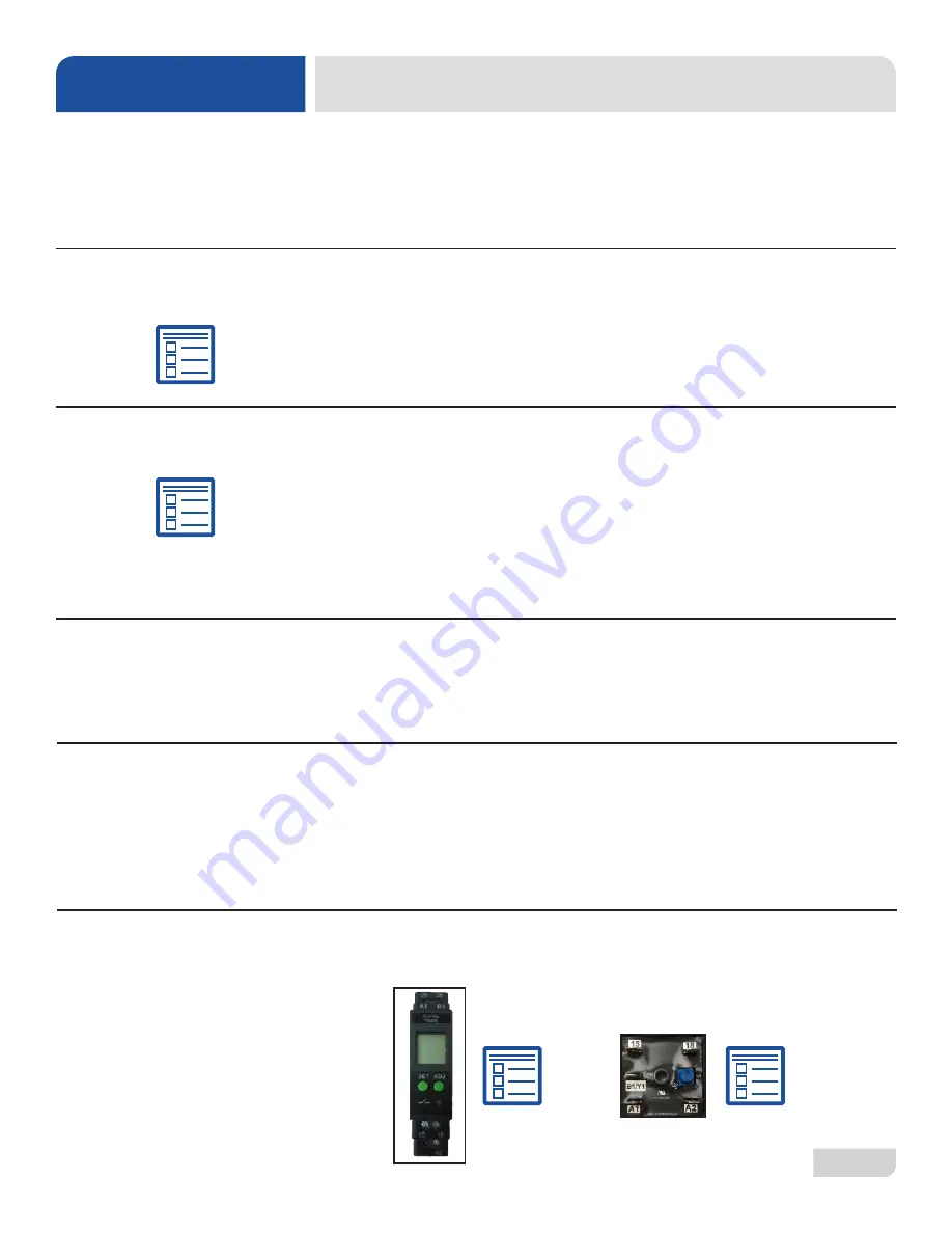
Determine which exhaust fan timer is on the machine (located in the control box)
and click the instructions icon beside that timer to access programming instructions.
STEAM LINE
CONNECTION
INSTRUCTIONS
INSTALLATION
EXHAUST FAN
TIMER
Содержание TEMPSTAR HH S
Страница 35: ...07610 002 23 32 AD 26 1 5 4 2 3 6 7 10 8 9 HOOD PARTS ...
Страница 61: ...07610 002 23 32 AD 52 VER SYSTEM PARTS 18 24 23 12 11 16 17 14 21 22 20 19 27 28 29 ...
Страница 67: ...07610 002 23 32 AD 58 SCHEMATICS HH E VER 208 230 V NEW RINSE TANK ...
Страница 68: ...59 07610 002 23 32 AD SCHEMATICS HH E VER 460 V NEW RINSE TANK ...
Страница 69: ...07610 002 23 32 AD 60 SCHEMATICS HH E VER 208 230 V OLD RINSE TANK ...
Страница 70: ...61 07610 002 23 32 AD SCHEMATICS HH E VER 460 V OLD RINSE TANK ...
Страница 71: ...07610 002 23 32 AD 62 SCHEMATICS NB 208 230 V ...
Страница 72: ...63 07610 002 23 32 AD SCHEMATICS NB 460 V ...
Страница 73: ...07610 002 23 32 AD 64 SCHEMATICS HH S 208 230 V ...
Страница 74: ...65 07610 002 23 32 AD SCHEMATICS SDI OPTIONS ...
Страница 75: ......


