background image

C

Ri

ght Si

de

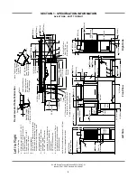
34 [864mm]

8

1

2

 [217mm]

21 [533mm]

25 [635mm]

12 [307mm]

25 [635mm]

B

Dish Clearance

Drive Unit

Le

ft S

ide

66

1

2

 [1692mm]

3 [79mm]

1

2

 [15mm]

84 [2134mm]

A

G

F

With Doors Open

Rear of

Machine

6 [152mm]

Right to Left

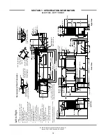
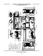
Legend

A - Machine water inlet 3/4"

 NPT, 180°

F

     Hi-temp,140°F Low-temp minimum

B - Electrical connection

C - Drain connection 1-1/2"

 NPT

D - Vent collar - Optional

E - Vent cowl standard

F - Prewash water inlet 3/4"

 NPT

     110°F-140°

F

G - Cold water thermostat plumbing

      connection 3/4"

 NPT - Optional

Note: All vertical dimensions are +/- 1/2"

from floor due to adjustable bullet feet.

1 [25mm]

Drive Unit

Front Vi

e

w

75

1

2

 [1919mm]

62

1

2

 [1590mm]

29 [737mm]

6 [152mm]

10 [254mm]

C

A

B

4 [102mm]

7 [178mm]

D

E

8 [203mm]

42 [1067mm]

41 [1041mm]

24 [610mm]

10

1

4

 [260mm]

F

24 [610mm]

G

23

1

2

 [599mm]

60

1

4

 [1530mm]

66

1

4

 [1684mm]

Floor Sink Or Drain

With 3"

 (76 mm)

Minimum Drain Line

25 [635mm]

4 1/2 [114mm]

8

1

4

 [210mm]

21 [533mm]

B

A

F

Table to Table

Overall

Prewash Plan View Section

with Cold Water Thermostat

16

3

4

 [425mm]

16

1

4

 [415mm]

F

G

82 [2086mm]

74 [1883mm]

66 [1679mm]

3/4"

 (19 mm)

Table Turndown

Flange 3/4"

 Max

21"

 (533 mm)

Rack Rail Height

Above Dishtable

1/4"

 (6mm) - 5/16"

 (8mm)

Rack Rail

Tu

b

Table

Use Silicone Sealer

Between Table and

Lip of Machine to

Prevent Leakage

Recommended Table Fabr

icat

ion

Note: Tub Will Accept

a Table Flange

Up to 24 7/8"

(632 mm)

4"

 (102 mm) wide x 16"

 (406 mm)

long cutout in Vent Cowl/Splash

Shield. Shipped with Cover Plate.

22 [559mm]

44 [1121mm]

Base Unit

Prewash

SECTION 1: SPECIFICATION INFORMATION

AJ-66T ELECTRIC - RIGHT TO LEFT

11

AJ-44T Series Technical Manual 7610-003-07-21

Issued: 03-21-2006  Revised: 09-29-2007

Содержание AJ-44TE

Страница 1: ...06 523 9795 Fax 606 523 9196 www jacksonmsc com AJ 44T SERIES RACK CONVEYOR DISHMACHINE September 29 2007 P N 7610 003 07 21 Revision C AJ 44T SERIES AJ 44TE AJ 44TG AJ 44TS AJ 66T SERIES AJ 66TE AJ 66TG AJ 66TS AJ 80T SERIES AJ 80TE AJ 80TS AND ASSOCIATED OPTION PACKAGES INCLUDING SIDE LOADER ...

Страница 2: ...ion if serial number has been removed or altered or if unit is used for purpose other than it was origi nally intended TRAVEL LIMITATIONS Jackson MSC limits warranty travel time to 2 two hours and mileage to 100 one hundred miles Jackson MSC will not pay for travel time and mileage that exceeds this or any fees such as those for air or boat travel without prior authorization WARRANTY REGISTRATION ...

Страница 3: ...PRODUCT FAILURE TO DO SO WILL VOID THE WARRANTY LLAME AL 1 888 800 5672 PARA REGISTRAR ESTE PRODUCTO AL NO HACERLO LA GARANTIA SERA ANULADA S V P APPELER 1 888 800 5672 POUR ENREGISTRER CE PRODUIT LA GARANTIE SERA ANNULEE POUR TOUT PRODUIT NON ENREGISTREE ...

Страница 4: ...laced rinse drain weldment 05700 021 68 28 with 05700 002 51 12 Added wash rinse and psi decals Changed the door assemblies Added the rinse fill motor assembly Added Gas Models C 3 21 2006 MAW 7571 Change to new layout Change themostats and add replacement kits PG 100 04 19 2007 MAW 7898 Added 09905 003 32 20 fan load decal 4 thru 21 91 09 29 2007 MAW N A Updated dimension pages Removed alternate ...

Страница 5: ...C provides technical support for all of the dishmachines detailed in this manual We strongly recommend that you refer to this manual before making a call to our technical support staff Please have this manual with you when you call so that our staff can refer you if necessary to the prop er page Technical support is available from 8 00 a m to 5 00 p m EST Monday through Friday Technical support is...

Страница 6: ... Dimensions 24 II INSTALLATION OPERATION INSTRUCTIONS Installation Instructions 26 Curtain Installation Diagram 29 Deliming Operations 30 Side Loader Installation Operation Instructions 31 Dishmachine Operating Instructions 32 Detergent Control 34 Striker Plate Limit Switch Installation Instructions 35 III PREVENTATIVE MAINTENANCE General Maintenance 37 Lubrication Chart for Drive Gear 38 Drive Mo...

Страница 7: ...sembly 83 AJ 66T Rack Rail Assemblies 84 AJ 80T Rack Rail Assemblies 85 Miscellaneous Parts Weldments 86 Strainers 87 Float Switch Components Scrap Baskets 88 Curtains Tub Magnets 89 Vent Cowl Assembly Vent Scoop Option 90 Exhaust Fan Control Limit Switch Options 91 SIDE LOADER SECTION Side Loader Track Assembly Leg Replacements 92 Side Loader Pawl Bar Assemblies Strainer Magnet 93 Side Loader Paw...

Страница 8: ...30 Volt 60 Hz 3 Phase 111 460 Volt 60 Hz 3 Phase 112 AJ 66TS AJ 80TS 208 230 Volt 60 Hz 1 Phase 113 208 230 Volt 60 Hz 3 Phase 114 460 Volt 60 Hz 3 Phase 115 Conveyor Side Loader Drain Quench Schematics 116 Exhaust Fan Hook Up Schematics 117 VIII JACKSON MAINTENANCE REPAIR CENTERS 118 TABLE OF CONTENTS v ...

Страница 9: ...1 SECTION 1 SPECIFICATION INFORMATION ...

Страница 10: ...R SPEED FPM AJ 44 66 80TE TG TS MACHINES 5 7 GALLONS PER RACK AJ 44 66 80TE TG TS MACHINES 69 WATER TEMPERATURES AJ 44 66 80TE TG TS MODELS PREWASH RECOMMENDED AJ 66 AJ 80 110 140 F WASH MINIMUM 160 F RINSE MINIMUM 180 F FLOW PRESSURE PSI 20 5 FLOWRATE GPM AJ 44 66 80TE TG TS 3 1 STEAM COIL TANK HEAT TS MODELS ONLY STEAM INLET PRESSURE PSIG 10 20 STEAM CONNECTION NPT 3 4 CONSUMPTION 15 PSIG lbs hr...

Страница 11: ... A 15 AMP AJ 44TS 230 3 60 N A 7 A 15 AMP AJ 44TS 460 3 60 N A 4 A 15 AMP AJ 66TE 208 1 60 N A 103 A 150 AMP AJ 66TE 230 1 60 N A 95 A 125 AMP AJ 66TE 208 3 60 N A 61 A 80 AMP AJ 66TE 230 3 60 N A 52 A 70 AMP AJ 66TE 460 3 60 N A 26 A 35 AMP AJ 66TG 208 1 60 N A 18 A 25 AMP AJ 66TG 230 1 60 N A 18 A 25 AMP AJ 66TG 208 3 60 N A 12 A 15 AMP AJ 66TG 230 3 60 N A 12 A 15 AMP AJ 66TG 460 3 60 N A 7 A 1...

Страница 12: ...mm 25 635mm 10 254mm 7 178mm D E A C A B 18 1 2 467mm 25 635mm 4 1 2 114mm 4 102mm Table to Table Overall With Doors Open Rear of Machine Dish Clearance 14 356mm Minimum 10 High Table Backsplash Scrap Trough 7 1 2 190mm C B Legend A Machine water inlet 3 4 NPT 180 F Hi temp 140 F Low temp minimum B Electrical connection C Drain connection 1 1 2 NPT D Vent collar Optional E Vent cowl standard Note ...

Страница 13: ... 737mm 6 152mm 7 1 2 193mm 21 533mm 25 635mm 25 635mm 10 254mm 7 178mm D E A C A B 18 1 2 467mm 25 635mm 4 1 2 114mm 4 102mm Table to Table Overall With Doors Open Rear of Machine Dish Clearance 7 1 2 190mm C B Legend A Machine water inlet 3 4 NPT 180 F Hi temp 140 F Low temp minimum B Electrical connection C Drain connection 1 1 2 NPT D Vent collar Optional E Vent cowl standard Note All vertical ...

Страница 14: ...ter inlet for gas booster heater H 3 4 NPT 180 F Water Outlet connection to line on dishmachine Connection hose provided by manufacturer J 3 4 NPT Gas Connection K 4 OD Vent pipe connection Flue to be installed to meet local codes by installing contractor Note All vertical dimensions are 1 2 from floor due to adjustable bullet feet 1 25mm K J H G 3 4 19 mm Table Turndown Flange 3 4 Max 21 533 mm R...

Страница 15: ...3 4 NPT 180 F Water Outlet connection to line on dishmachine Connection hose provided by manufacturer J 3 4 NPT Gas Connection K 4 OD Vent pipe connection Flue to be installed to meet local codes by installing contractor Note All vertical dimensions are 1 2 from floor due to adjustable bullet feet 60 1 4 1530mm 1 25mm 66 1 4 1684mm 4 102 mm wide x 16 406 mm long cutout in Vent Cowl Splash Shield S...

Страница 16: ...al E Vent cowl standard F 3 4 NPT Steam connection G 3 4 NPT Condensate return H Steam electrical connection J 1 NPT Steam connection K 3 4 Condensate connection L 3 4 NPT Incoming 110 F water connection M 3 4 NPT 180 F water to dishmachine Note All vertical dimensions are 1 2 from floor due to adjustable bullet feet 60 1 4 1530mm 8 204mm 7 178mm 10 254mm 12 1 2 316mm G F 17 1 2 445mm 4 102 mm wid...

Страница 17: ...wl standard F 3 4 NPT Steam connection G 3 4 NPT Condensate return H Steam electrical connection J 1 NPT Steam connection K 3 4 Condensate connection L 3 4 NPT Incoming 110 F water connection M 3 4 NPT 180 F water to dishmachine Note All vertical dimensions are 1 2 from floor due to adjustable bullet feet 60 1 4 1530mm 8 204mm 7 178mm 10 254mm 12 1 2 316mm G F 17 1 2 445mm 4 102 mm wide x 16 406 m...

Страница 18: ... 3 4 NPT 180 F Hi temp 140 F Low temp minimum B Electrical connection C Drain connection 1 1 2 NPT D Vent collar Optional E Vent cowl standard F Prewash water inlet 3 4 NPT 110 F 140 F G Cold water thermostat plumbing connection 3 4 NPT Optional Note All vertical dimensions are 1 2 from floor due to adjustable bullet feet 82 2086mm 74 1883mm 44 1121mm 3 4 19 mm Table Turndown Flange 3 4 Max 21 533...

Страница 19: ...67mm 41 1041mm 24 610mm 10 1 4 260mm F 24 610mm G 23 1 2 599mm 60 1 4 1530mm 66 1 4 1684mm Floor Sink Or Drain With 3 76 mm Minimum Drain Line 25 635mm 4 1 2 114mm 8 1 4 210mm 21 533mm B A F Table to Table Overall Prewash Plan View Section with Cold Water Thermostat 16 3 4 425mm 16 1 4 415mm F G 82 2086mm 74 1883mm 66 1679mm 3 4 19 mm Table Turndown Flange 3 4 Max 21 533 mm Rack Rail Height Above ...

Страница 20: ...ion C Drain connection 1 1 2 NPT D Vent collar Optional E Vent cowl standard F 3 4 NPT 180 F Water Inlet for wash tank fill final rinse tank heating From gas booster heater Interconnecting hose provided by manufacturer G 3 4 NPT 140 F Water inlet for gas booster heater H 3 4 NPT 180 F Water Outlet connection to line on dishmachine Connection hose provided by manufacturer J 3 4 NPT Gas Connection K...

Страница 21: ...plash Shield Shipped with Cover Plate 22 559mm 44 1121mm Base Unit Prewash Left to Right Legend A Machine water inlet 3 4 NPT 180 F Hi temp 140 F Low temp minimum B Electrical connection C Drain connection 1 1 2 NPT D Vent collar Optional E Vent cowl standard F 3 4 NPT 180 F Water Inlet for wash tank fill final rinse tank heating From gas booster heater Interconnecting hose provided by manufacture...

Страница 22: ...le and Lip of Machine to Prevent Leakage Recommended Table Fabrication Note Tub Will Accept a Table Flange Up to 24 7 8 632 mm Left to Right Legend A Machine water inlet 3 4 NPT 180 F Hi temp 140 F Low temp minimum B Electrical connection C Drain connection 1 1 2 NPT D Vent collar Optional E Vent cowl standard F 3 4 NPT Steam connection G 3 4 NPT Condensate return H Steam electrical connection J 1...

Страница 23: ...0 1 4 260mm F 24 610mm G 23 1 2 599mm 60 1 4 1530mm 66 1 4 1684mm Floor Sink Or Drain With 3 76 mm Minimum Drain Line 25 635mm 4 1 2 114mm 8 1 4 210mm 21 533mm B A F Table to Table Overall Prewash Plan View Section with Cold Water Thermostat 16 3 4 425mm 16 1 4 415mm F G 82 2086mm 74 1883mm 66 1679mm 3 4 19 mm Table Turndown Flange 3 4 Max 21 533 mm Rack Rail Height Above Dishtable 1 4 6mm 5 16 8m...

Страница 24: ... Optional Note All vertical dimensions are 1 2 from floor due to adjustable bullet feet 88 2238mm 44 1121mm 3 4 19 mm Table Turndown Flange 3 4 Max 21 533 mm Rack Rail Height Above Dishtable 1 4 6mm 5 16 8mm Rack Rail Tub Table Use Silicone Sealer Between Table and Lip of Machine to Prevent Leakage Recommended Table Fabrication Note Tub Will Accept a Table Flange Up to 24 7 8 632 mm 1 25mm 66 1 4 ...

Страница 25: ... A F Table to Table Overall Prewash Plan View Section with Cold Water Thermostat 16 3 4 425mm 16 1 4 415mm F G 88 2238mm 3 4 19 mm Table Turndown Flange 3 4 Max 21 533 mm Rack Rail Height Above Dishtable 1 4 6mm 5 16 8mm Rack Rail Tub Table Use Silicone Sealer Between Table and Lip of Machine to Prevent Leakage Recommended Table Fabrication Note Tub Will Accept a Table Flange Up to 24 7 8 632 mm 4...

Страница 26: ...ive Unit L 14 356mm Minimum 10 High Table Backsplash Scrap Trough Floor Sink Or Drain With 3 76 mm Minimum Drain Line Legend A Machine water inlet 3 4 NPT 180 F Hi temp 140 F Low temp minimum B Electrical connection C Drain connection 1 1 2 NPT D Vent collar Optional E Vent cowl standard F 3 4 NPT 180 F Water Inlet for wash tank fill final rinse tank heating From gas booster heater Interconnecting...

Страница 27: ...ight Side 34 864mm 8 1 2 217mm 21 533mm 25 635mm 12 307mm 25 635mm B Dish Clearance 6 155mm J K G H 36 914mm 31 1 4 797mm 6 1 2 165mm 6 152mm 26 1 2 673mm Legend A Machine water inlet 3 4 NPT 180 F Hi temp 140 F Low temp minimum B Electrical connection C Drain connection 1 1 2 NPT D Vent collar Optional E Vent cowl standard F 3 4 NPT 180 F Water Inlet for wash tank fill final rinse tank heating Fr...

Страница 28: ... D E C A B 41 1039mm 8 206mm G 24 610mm 23 1 2 600mm O 18 457mm 41 1043mm 4 102mm Drive Unit N 14 356mm Minimum 10 High Table Backsplash Scrap Trough Floor Sink Or Drain With 3 76 mm Minimum Drain Line 38 966mm 11 1 4 285mm 13 1 2 345mm 23 3 4 604mm 13 1 2 345mm 4 1 4 110mm 5 3 4 148mm 8 1 2 218mm 6 1 4 159mm M K L J F H 17 1 2 445mm 12 1 2 316mm F 16 3 8 417mm 15 3 4 400mm 11 5 8 295mm 6 3 8 162m...

Страница 29: ...75 1 2 1921mm 60 1 4 1529mm 62 3 4 1592mm 29 735mm 10 1 4 260mm 6 152mm 10 254mm G A B 41 1042mm C 23 1 2 598mm 24 611mm G 42 1069mm 4 102mm Drive Unit F D E 8 203mm 41 1041mm 38 965mm 7 178mm Right Side Legend A Machine water inlet 3 4 NPT 180 F Hi temp 140 F Low temp minimum B Electrical connection C Drain connection 1 1 2 NPT D Vent collar Optional E Vent cowl standard F Prewash water inlet 3 4...

Страница 30: ... loader CONVEYOR DISHWASHER LENGTH 8 or 15 depending on the width of the side loader 4 1 2 MINIMUM 25 DISHWASHER 5 12 1 2 14 1 2 29 1 1 2 TABLE ROLL 20 3 4 OPENING 1 A A 1 2 MINIMUM 1 2 DISHTABLE USE SILICONE BETWEEN TABLE AND LIP OF SIDE LOADER TO PREVENT LEAK AGE WALL OF SIDE LOADER SECTION A A CENTER LINE DISHMACHINE SPLASH SHIELD VENT CONNECTION OPENING 1 1 2 DRAIN CONNECTED TO DISHMACHINE DRA...

Страница 31: ... the side loader 23 or 30 depending on the width of the side loader CONVEYOR DISHMACHINE LENGTH 4 1 2 MINIMUM 12 1 2 25 DISHWASHER 5 1 1 2 TABLE ROLL 20 3 4 OPENING 1 1 2 MINIMUM DISHTABLE 1 2 WALL OF SIDE LOADER USE SILICONE BETWEEN TABLE AND LIP OF SIDE LOADER TO PRE VENT LEAKAGE SECTION A A CONVEYOR DISHMACHINE CENTER LINE DISHMACHINE VENT CONNECTION OPENING SPLASH SHIELD A A 1 1 2 DRAIN CONNEC...

Страница 32: ...TALLED DIMENSIONS 24 Refer to chart above 34 23 or 30 depending on the width of the side loader 10 4 23 SIDE LOADER DIMENSIONS 30 SIDE LOADER DIMENSIONS MODEL AJ 44T AJ 66T AJ 80T MODEL AJ 44T AJ 66T AJ 80T DIMENSIONS 75 97 111 DIMENSIONS 82 104 118 Left to Right installation shown for reference NOTE ALL DIMENSIONS ARE TYPICAL ...

Страница 33: ...25 SECTION 2 INSTALLATION OPERATION INSTRUCTIONS ...

Страница 34: ...lves that are fouled as a result of foreign matter left in the water line and any expenses resulting from this fouling are not the responsibility of the manufacturer Water hardness should be a maximum of 6 grains per gallon Harder water should be treated prior to using the machine Iron in the water supply can cause staining A filter designed to remove iron from the supply water is highly recommend...

Страница 35: ...e pre punched holes in the back of the control box Route power wires and connect to power block and grounding lug Install the service wires L1 L2 and L3 3 phase only to the appropriate terminals as they are marked on the terminal block Install the grounding wire into the lug provided Tighten the connections It is recommended that DE OX or another similar anti oxidation agent be used on all power c...

Страница 36: ...Control The 1 8 brass plugs on the incoming plumbing rinse injector may be removed to install sanitizer and rinse aid injection fittings All wires for the chemical injectors should be routed through one of the extra openings in the back of the control box Terminals in the control box marked CVS provide a constant voltage signal whenever the drive motor is operating Terminals in the control box mar...

Страница 37: ...S 29 44 L R L S S L L 21 12 12 21 21 21 21 12 12 L L S S R L 21 21 12 12 21 L L S S L R L 66 12 S 80 S 12 L R S S L L 12 12 21 21 S 12 L R L S S L L 21 12 12 21 21 21 21 12 12 21 L L S S L R L HOODED SIDE LOADER UNHOODED SIDE LOADER UNHOODED SIDE LOADER HOODED SIDE LOADER ELECTRIC STEAM MACHINES Please refer to the chart for placement of the curtains ...

Страница 38: ...on 2 Disconnect or turn off all chemical feeder pumps 3 Close all doors after adding the deliming solution 4 Run the machine for the recommended period of time 5 Turn the unit off and open the doors 6 Wait five minutes then inspect the inside of the machine If the machine is not delimed run another time cycle as per the deliming solution s instructions 7 When clean drain and re fill the machine 8 ...

Страница 39: ...wing unscraped dishes into the machine simply defeats the purpose altogether of washing the ware Scraps should be removed from ware prior to being loaded into a rack Pre rinsing and pre soaking are good ideas especially for silverware and casserole dishes Place cups and glasses upside down in racks so that they do not hold water during the cycle The dishmachine is meant not only to clean but to sa...

Страница 40: ...not come out clean and the efficiency of the dishmachine will be reduced It is important to remember that a dishmachine is not a garbage disposal and that simply throwing unscraped dishes into the machine simply defeats the purpose altogether of washing the ware Scraps should be removed from ware prior to being loaded into a rack Pre rinsing and pre soaking are good ideas especially for silverware...

Страница 41: ... scrap basket strainer Remove the wash and if equipped the prewash arms and verify that the nozzles and arms are free from obstructions Flush the arms with fresh water Remove the pump suction strainers and clean out as required Remove the rinse tray assembly and clean Remove the curtains and scrub with a mild detergent and warm water Wipe out the inside of the unit and then reassemble with the com...

Страница 42: ...for operators Using too much detergent has as detrimental effects as using too little The proper amount of detergent must be used for job It is important to remember that certain menu items may require extra detergent by their nature and personnel need to be made aware of this Experience in using the dishmachine under a variety of conditions along with good training in the operation of the machine...

Страница 43: ... the switch 2 Parts of the table switch are mounted in the dishtable at the end of the table and under the table See the drawing s for the relationship of the switch to the table 3 Move the limit switch as far down on the two slots as possible and see that the limit switch is straight on the base plate This might require adjustment of the nut on the connector for the limit switch 4 Then adjust the...

Страница 44: ...36 SECTION 3 PREVENTATIVE MAINTENANCE ...

Страница 45: ...work harder and decreases efficiency Again it is important to remind operators that trying to perform corrective maintenance on the dishmachine could lead to larg er problems or even cause harm to the operator If a problem is discovered secure the dishmachine using proper shut down procedures as listed in this manual and contact Jackson Some problems however may having nothing to do with the machi...

Страница 46: ...MA 7 Gear Oil AGMA 8 Gear Oil AGMA 7 Gear Oil N A N A Castrol Tribol 800 220 Tribol 1105 7C Tribol 1105 8C Tribol 1105 7C Tribol 800 680 Tribol 800 460 Chevron Tegra 220 Cylinder Oil W460 Cylinder Oil W680 Cylinder Oil W460 Tegra 680 Tegra 460 Conoco Syncon R O Inca Oil 460 Inca Oil 680 Inca Oil 460 N A Syncon R O 220 460 Exxon Esso Teresstic SHP220 Spartan EP 460 Spartan EP 680 Spartan EP 460 Ter...

Страница 47: ...ever continuous operation above 225 F may cause damage to seals or other components It is recommended that the initial oil be changed or filtered after the first 1500 hours of operation to remove metal particles that accumulate during break in Subsequent oil changes should be made after 5000 hours operation if units are operating in a clean environment This can be extended to 10 000 hours if using...

Страница 48: ...40 SECTION 4 TROUBLESHOOTING SECTION ...

Страница 49: ...ressure Verify that incoming water pressure during fill is 20 5 PSI 2 Incoming water solenoid is clogged Verify that debris is not entrapped in valve If so remove debris Problem Low wash tank temperature 1 Low incoming water temperature Verify that the incoming water temperature matches what is indicated on the machine data plate 2 Heater not energizing Verify that the wash tank heater is operatin...

Страница 50: ...Spotting of silverware glasses and dishes 1 Incorrect final rinse temperature Verify that the rinse water temperature matches that which is listed on the machine data plate 2 Clogged wash and or rinse nozzles and arms Remove the arms and verify that they and their nozzles are from debris 3 Excessively hard water Install a water softener to reduce hardness 4 Loss of water pressure due to clogged ob...

Отзывы: