background image

© 2006 Jackson-Labs

43

FireFox Synthesizer User Manual

be used in any digital logic application up to 390MHz, far outperforming competitive solutions 
allowing it to be used in SDR, DDR, QDR memory interfaces, or as CPU master clock drivers.
* 50 Ohm AC-coupled spectrally pure RF sine-wave output from 2MHz to 1640MHz. Used in any 
type of communication applications that require a low phase-noise, spectrally pure output signal. 
Adjustable from typically less than -40dbm to up to +18dbm depending on the frequency (in relative 
output mode, when setting 0% to 100% output power).
* LVDS digital differential, 50 Ohm signal on two SMA connectors. Typically terminated by a 100 
Ohm resistor between the two signals. This signal is used in modern high-speed interfaces such as 
LCD panels, FPGAs, memories etc. These signals can also be used as standard RF signals when 
connected via an AC coupler (output at ca. -3 to -5dbm), or as PECL differential signals when 
terminated to ground via two 50 Ohm resistors. The signal is being driven from 10MHz to 1640MHz, 
with an under-range down to 2MHz.
* BNC connector with a 10MHz very low phase-noise Reference clock output, digital CMOS 3.3V 
level. This signal in combination with a CMOS 3.3V level 1PPS output is similar to other frequency 
references on the market, and may be used as an in-house frequency standard to drive other 
instruments for better than 10^-12 long term performance.
* Broadband 2GHz analog mixer. A general-purpose broadband mixer with over 350MHz bandwidth 
is available on the front panel. This can be used in receiver, transmitter, or transponder applications. 
Any RF signal up to 2GHz may be mixed with an LO signal up to 2GHz, and produce a 350MHz 
bandwidth IF signal. The RF signal input can be driven by a -20dbm to +10dbm signal. The LO input 
can typically be driven by the Synthesizers’ own RF-type output (see above) at 0dbm. To avoid 
damage, a signal amplitude maximum of +10dbm should not be exceeded on the RF and LO inputs.

3.3.3 Can the FireFox system keypad be locked? 

Yes, the FireFox keypad can be locked with jumper JP11 located on the FireFox main PCB. 

3.3.4 How come the Frequency Display doesn’t let me select 

the exact Frequency I need? 

You probably have turned off Fractional-N mode (see also “Resolution” FAQ under Performance 
section). With fractional-N mode disabled, the frequency granularity that can be generated is 1/65536 
of the granularity when the fractional-N mode is enabled.
A warning message in the LCD display shows “FractOff” to indicate that the fractional-N mode is 
turned off.
When the fractional-N mode is turned off, the frequency will still be increased or decreased in 10µHz 
steps when pressing the UP/DOWN buttons, but the display will show the actual frequency that can 
be generated by the DDS (closest match to the desired frequency) once the button is released.
The advantage of turning off the fractional-N mode is that the system generates an exact 
mathematically deterministic frequency without residual, fractional errors that are present in 
fractional-N mode. 

Содержание FireFox

Страница 1: ...FireFox Synthesizer User Manual Document 0012008 Version 004 Date 10 April 2008...

Страница 2: ...FireFox Synthesizer User Manual Copyright 2008 Jackson Labs...

Страница 3: ...uick Start Instructions 5 1 4 1 Connecting the instrument 5 1 4 2 Initializing the GPS 5 1 4 3 Setting up the GPS 6 1 4 3 1 GPS Time Offset 6 1 4 3 2 Selecting Metric US Mode 6 1 4 3 3 GPS Auto Survey...

Страница 4: ...or Outputs 22 1 6 3 GPS Disciplined OCXO Reference 23 1 6 4 DDS Synthesizer 24 1 6 5 RF Output Buffer 24 1 6 6 User Interface 25 1 6 7 NV memory 25 1 6 8 Frequency Sweeping 25 1 6 9 Differences betwee...

Страница 5: ...1 3 1 Overview 41 3 2 General FAQs 41 3 2 1 How can the FireFox Synthesizers offer such high performance for such a low price 41 3 2 2 How did you decide what features to include in the FireFox synthe...

Страница 6: ...s in the LCD display indicate 49 3 6 Performance FAQs 50 3 6 1 How does the FireFox Synthesizer offer such wide bandwidth 50 3 6 2 How can spur performance be increased even further 50 3 6 3 Does the...

Страница 7: ...eed expensive physics package replacements every 5 years or less and provides better long term time base accuracy than non GPS disciplined Cesium references This manual describes the FireFox GPS disci...

Страница 8: ...2 Limitation of Warranty The foregoing warranty shall not apply to defects resulting from improper or inadequate maintenance by the Customer Customer supplied software or interfacing unauthorized mod...

Страница 9: ...cable with the third wire firmly connected to an electrical ground safety ground at the power outlet Any interruption of the protective grounding conductor or disconnection of the protective earth ter...

Страница 10: ...line voltages or frequencies in excess of those stated on the data plate may cause unsafe leakage currents 1 3 8 Do not substitute parts or modify the Instrument Do not install substitute parts or pe...

Страница 11: ...rranty 1 4 2 Initializing the GPS Every time the FireFox unit is moved it is recommended to enable the GPS Automatic Site Survey mode or AutoSurvey in order to reacquire its exact new position The aut...

Страница 12: ...he SETUP GPS GPS TIME OFFSET menu and select between 12 to 12 hours of time offset to Greenwich Mean Time GMT 1 4 3 2 Selecting Metric US Mode The unit may display GPS height time and date in either M...

Страница 13: ...o be selected from the front panel Check the frequency limit setting if you are not able to configure the unit to generate signals up to the 1 64GHz maximum frequency 1 4 5 Setting the RF Amplitude Th...

Страница 14: ...on the two LVDS connectors is approximately 300mV peak on each output and this may be used to drive two independent analog inputs with ca 7dBm level when connected via AC coupling 1 4 6 2 Connecting a...

Страница 15: ...or resolution and also affects the output phase noise and frequency drift Select FRACT ON to set the DDS to 48 bit Frequency mode or FRACT OFF to turn off the Fractional N mode and set the unit to 32...

Страница 16: ...ser may limit the maximum possible analog RF Output Power that can be set via the front panel keys in the frequency setting menu This setting will also affect sweep modes and memory recall modes The u...

Страница 17: ...tes then comparing this value to the present phase offset and calculating the error in one minute updates The OCXO temperature shown is measured at the outside of the metal cage of the OCXO and should...

Страница 18: ...an I Q baseband DVB T video signal to an RF carrier of 61 25MHz simply set the RF output of the FireFox Signal Generator to 61 25MHz feed the RF output into the LO Mixer input set the RF output ampli...

Страница 19: ...any data by pressing the EXIT MENU button All FireFox settings such as Maximum Frequency Power settings the Frequency Power Unit output power and other settings are saved in these memory locations Pl...

Страница 20: ...operating for several weeks are 5E 010 for the default OCXO option and 5E 011 for the Double Oven Ultra High Stability OCXO option 1 4 14 Advanced GPS Setup 1 4 14 1 Factory Reset Pressing the enter b...

Страница 21: ...et the port you choose and select 9600 Baud communications 4 You should now see Satellite status information and be able to control the receiver with the WinOncore12 program Settings such as Satellite...

Страница 22: ...s per Second Linear and Logarithmic 0 1 1000s F1 F2 or F1 F2 F1 Leveled between 40dBm and 10dBm better than 1dBm level accuracy Time Base Stability Aging Warm up time from cold boot 20 Degree Celsius...

Страница 23: ...tive mode 0 100 absolute mode power absolute mode accuracy at 0dBm output up to 18dBm 40dBm to 10dBm better than 0 5dBm typi cally LVDS Output Common mode voltage 100 Ohm terminated SMA to SMA connect...

Страница 24: ...e using a TSC 5110A Time Interval Analyzer 1PPS GPS Port CMOS compatible BNC output on rear panel Rising edge synchronized to UTC Do not terminate use a 50 Ohm open ended cable Rising edge can be shif...

Страница 25: ...ement intervals when locked to GPS The rear panel 1PPS output of the FireFox Signal Generator is driven by the Motorola M12 GPS timing receiver The 1PPS BNC output is only active when the unit is lock...

Страница 26: ...achieves a better than 10 12 Stratum 1 long term accuracy The short term accuracy when locked to GPS is typically better than 5x10 10 when measured in 30 minute intervals see Figure 1 2 Please note th...

Страница 27: ...and debugging PLL circuits and driving mixers and other RF equipments local oscillator inputs With the frequency sweep features it is possible to use the FireFox synthesizer to design Microwave equip...

Страница 28: ...bm output power by the FireFox signal generator The output phase can be controlled in 0 1 degree steps from 180 to 180 degrees allowing very precise alignment of signals for quadrature type applicatio...

Страница 29: ...is accurate to within 20ns of UTC is available on this connector Typically an unterminated 50Ohm coax cable is used to provide this signal to optional external Caesium or Rubidium atomic frequency ref...

Страница 30: ...signal phase arbitrarily from 180 to 180 degrees with 0 1 degree resolution 1 6 5 RF Output Buffer The FireFox synthesizer has multiple digital outputs and one analog RF signal output This RF output i...

Страница 31: ...NV memory even when power is removed from the system 1 6 8 Frequency Sweeping The unit can be used for arbitrary frequency sweeping with linear or logarithmic sweep modes Start Stop and sweep speed s...

Страница 32: ...FireFox Synthesizer User Manual 26 2006 Jackson Labs Figure 1 7 FireFox OEM Module System Board Bottom...

Страница 33: ...would use the FireFox analog RF output as the Local Oscillator LO driver of the FireFox mixer The RF input of the mixer could then be connected to an external LNA buffer and band select filter The Int...

Страница 34: ...FireFox Synthesizer User Manual 28 2006 Jackson Labs...

Страница 35: ...ing the SCPI protocol syntax can be found on the following web site http www scpiconsortium org Please refer to the document SCPI 99 pdf for details regarding individual SCPI command definitions A bas...

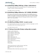
Страница 36: ...eFox Synthesizer Firmware Rev x x RST This command sets back the default values of the Frequency and Sweep subsystem No signal is being generated Power is set to the minimum of 40dBm and the phase off...

Страница 37: ...ns are CW FIXed numeric_value unit MODE CW FIXed SWEep CENTer numeric_value unit SPAN numeric_value unit STARt numeric_value unit STOP numeric_value unit 2 5 1 1 1 SOURce FREQuency CW The Continuous W...

Страница 38: ...t value is set to 0Hz 2 5 1 1 6 SOURce FREQuency STOP numeric_value This command sets the Stop frequency for the sweep configuration Changing this value will affect Center and Span in the following wa...

Страница 39: ...l affect the LVDS CMOS and RF outputs of the FireFox simultaneously In the Software Controlled sweeping mode the microcontroller controls the frequency of the DDS and changes it incrementally at high...

Страница 40: ...frequency sweep when the command INITiate IMMEdiate has been issued This command can be issued at any time during a sweep but it will only be activated after the next trigger event The time unit is i...

Страница 41: ...decrease in the opposite direction In this case the total duration of the sweep is doubled Upon RST the direction is set to UP 2 5 2 10 SOURce SWEep COUNt numeric value This command determines the nu...

Страница 42: ...ion STEPped SOURce SWEep POINTs 3801 SOURce SWEep DWELl 1 e 6 SOURce COUNt 10 OUTPut ON INITiate IMMe Alternative abbreviated style resulting in the same output sweep FREQ MODE SWE STAR 10Mhz STOP 390...

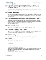
Страница 43: ...e defined in the interval PI PI radians or 180 180 Degrees On RST this value is set to 0 2 5 5 Output Subsystem This command controls the RF output connector of the FireFox Signal Generator 2 5 5 1 OU...

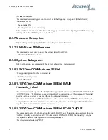
Страница 44: ...r this command are BAUD numeric_value ECHo ON OFF 2 5 8 1 1 SYSTem COMMunicate SERial BAUD numeric_value This command sets the speed of the RS232 The supported Baud rates are 9600 19200 38400 57600 an...

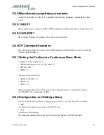
Страница 45: ...may be used to operate the FireFox Signal Generator 2 6 1 Setting the FireFox into Continuous Wave Mode Complete command syntax style SOURce FREQuency CW 123 456 Mhz cr OUTPut ON POWer 0 Alternative a...

Страница 46: ...FireFox Synthesizer User Manual 40 2008 Jackson Labs SOURce POWer...

Страница 47: ...duce the component count and thus cost while simultaneously increasing the units reliability Only standard off the shelf components are used to guarantee a long life and support time of the unit Other...

Страница 48: ...Desktop unit uses the same FireFox OEM board that is also sold separately The desktop unit includes a Swiss made enclosure a power supply an LCD Display a Keypad and external connectors for all the I...

Страница 49: ...2GHz analog mixer A general purpose broadband mixer with over 350MHz bandwidth is available on the front panel This can be used in receiver transmitter or transponder applications Any RF signal up to...

Страница 50: ...nder scan mode Operation of the LVDS outputs in under scan mode cannot be guaranteed and the LVDS LED is thus turned off The CMOS output is driven in over scan mode between 350MHz and 390390MHz and th...

Страница 51: ...Maximum power levels in relative mode typically range from 8dBm to 18dBm depending on the output frequency Absolute mode is used when highly accurate power levels are required Absolute mode sets the o...

Страница 52: ...ived RF input signal is then connected to the RF input Mixing the 1 5GHz LO frequency with the 1 4GHz RF signal will generate a 100MHz mixing product the Intermediate Frequency or IF signal which is b...

Страница 53: ...alibrate itself this process will take several hours to complete The calibration parameters are stored in its internal Flash memory after the calibration process completes 3 5 GPS Receiver FAQs These...

Страница 54: ...n be checked and controlled via a simple null modem serial cable Antenna cable offset satellite mask angles timing information satellite health information as well as GPS vs UTC time base settings are...

Страница 55: ...ming receiver is typically stationary and thus allows for much smaller bandwidth tracking filters increasing the timing solution accuracy significantly Comparable navigational receivers have a typical...

Страница 56: ...duce out of band spurs These filters can be designed with public domain software see for example Elsie an easy to use filter designer available at www tonnesoftware com or these can be purchased off t...

Страница 57: ...ional frequency step that can be generated in Fractional N mode is smaller than the 10 Hz step size of the FireFox system and the value displayed in the LCD can thus be used to estimate the frequency...

Страница 58: ...improve the frequency granularity of the output signal a fractional N mode can be enabled that increases the frequency resolution by an additional 16bits The disadvantage of this mode is that it is no...

Страница 59: ...rmed up for one to two hours before the auto calibration is started Plug in and turn on the power meter and plug in the FireFox synthesizer into the wall power outlet After warm up and prior to starti...

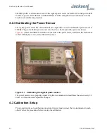
Страница 60: ...sor at 50MHz Plug in the 8482A power sensor into the Power Ref output of the power meter see Figure 4 1 Press the ZERO CAL button on the front of the power meter and follow the instructions in the LCD...

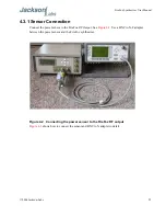
Страница 61: ...onnect the power sensor to the FireFox RF Output See Figure 4 2 Use a BNC to N F adapter between the power sensor and the FireFox synthesizer Figure 4 3 shows how to connect the sensor and BNC to N ad...

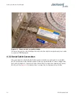
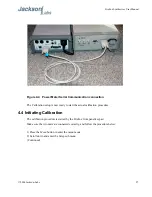
Страница 62: ...The power meter is controlled by the FireFox system controller via a serial port Use a standard RS 232 Null Modem cable with DB 9 female connectors a suitable RS 232 cable is shipped with the FireFox...

Страница 63: ...4 4 Initiating Calibration The calibration procedure is started by the FireFox front panel keypad Make sure the two units are connected correctly and follow the procedure below 1 Press the Menu button...

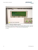
Страница 64: ...u Please note that the Calibration sub menu is on the sixth level and thus not visible in the LCD display until you scroll above the top menu item or below the bottom most menu item See Figure 4 5 on...

Страница 65: ...Manual 4 Enter the Calibration sub menu 5 Two menu items are shown see Figure 4 6 Setup and Debug Entering Setup will start the actual calibration procedure Debug is used for factory testing Continued...

Страница 66: ...lays information similar to Figure 4 7 The auto calibration procedure will take several hours to finish To avoid calibration errors do not disconnect any of the cables or touch any of the buttons on e...

Страница 67: ...mode by the FireFox RMT is displayed in the LCD and the unit is communicating as evidenced by the RX TX indicators The Power meter may sometimes also display the ERR indicator this indicator can be di...

Страница 68: ...THE UNITS POWER AFTER AND ONLY AFTER THE CALIBRATION IS FINISHED AND YOU SEE THE MESSAGE IN Figure 4 9 You can verify proper operation of the FireFox RF output using the power meter as it is connecte...

Отзывы: