15
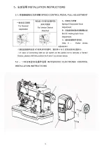
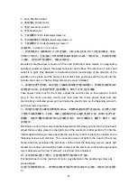
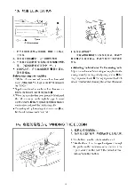
1
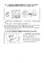
:机头
Machine Head
2
:直驱电机
Direct-motor
3
:电控
electronic control
4
:手轮
hand wheel
5
:上紧固螺钉
×2 On fastening screws ×2
6
:中间紧固螺钉
×2 Middle fastening screws ×2
7
:下紧固螺钉
×1 Under fastening screws ×1
安装说明:
Installation Instructions
一、把直驱电机
2
前端轴装上公三爪连接器,对应主轴上安装上母三爪连接及橡皮,电机
出线口方向向右,注意主轴上的平面和电机轴平面的方向关系(电机定位),然后将电机套
入主轴,上电机四个固定螺钉,电机安装完毕。
Mounted male three-jaw connector on front-end shaft direct drive motor2, Corresponding
spindle mounted on female three-jaw connector and rubber. The direction of motor and
outlet is to right. Pay attention to relationship (motor positioning) of the direction of the
spindle on the plane and the plane of the motor shaft, and then sets the motor into the
spindle, the motor on the four fixing screws, the motor installed.
二、取电控放置于电机旁,抽出电控上的编码器线插至电机编码器口,再取电机电源线头和
电控电源口对接,在电控内部穿上紧固螺钉
5
,螺钉上在穿上定位橡圈
Take power control next to the motor, extract the encoder line on the electronic control
plug to the motor encoder mouth, and then take the motor power head butt and
electronically controlled power port, put inside the electric hole on the fastening screws 5,
put the screws in position.
三、将电控的电机室对准电机慢慢套入机头,调整两条连接线置于电控右端,完全套入后穿
入电控中间紧固螺钉
6
不打紧,旋转上紧固螺钉与机头螺孔连接不打紧,再穿入电控下紧
固螺钉,检查并调整电控轮廓与机头轮廓配合适当,依次打紧螺钉
6
、螺钉
5
、螺钉
7
,电控
安装完毕。
Electronic control of the motor chamber alignment motor slowly set into the machine head,
adjust the two cable placed on the right side of the electronic control perfectly. Fit into the
intermediate fastening screws penetrate the electronic control not tight, the rotation on the
fastening screws and machine. The connection does not tight to the head of the screw
holes, and then penetrates the electronic control under the fastening screws, check and
adjusts the contour and machine head contours of the electronic control with appropriate
turn matter screws 6 screw 5, screws7, electrical control installed.
四、在电机后轴上套上手轮
4
,注意定位螺钉与轴平面对齐上紧。
Put hand wheel 4 on the rear axle of motor, pay attention to the positioning screw axis
plane aligned
在运行你的锁眼机之前
,
请仔细
阅
读本使用说明书内的指令并以正确、有
效
的方式里操
作
它
。
Содержание JK-T718E
Страница 1: ......
Страница 20: ......
Страница 23: ...17...
Страница 26: ...20...
Страница 34: ...28...
Страница 37: ...76...
Страница 39: ...2 MAIN SHAFT COMPONENTS 30 30 3 24 13 45 3...
Страница 41: ......
Страница 43: ......
Страница 45: ...5 NEEDLE BAR FRAME COMPONENTS 16 ss C 9...
Страница 47: ...6 OVEREDGING WIDTH ADJUSTING COMPONENTS 5 43 45 11...
Страница 51: ...8 BOBBIN THREAD TRIMMER COMPONENTS 1 35 39 40 20 18 21 21 1 15...
Страница 53: ...9 KNIFE BAR COMPONENTS 9 13 54 55 56 59 1_1 64 65 ___66 63 33 17...
Страница 54: ...18 P01011...
Страница 55: ...10 FEED CAM TRIPPING SEGMENT COMPONENTS 47 1 Q 17 12 25 6 6 50 19...
Страница 57: ...11 CONTROL BOX COMPONENTS...
Страница 59: ...12 SAFE PROTECTION COMPONENTS...
Страница 61: ...25...
Страница 63: ...14 THREAD TENSION COMPONENTS 2 54 27...


