background image

JABLOTRON FUTURA

INSTALLATION MANUAL

2/43

JABLOTRON LIVING TECHNOLOGY

1

1 .  

.  Introduction

Introduction

The subject of this installation manual is F u t u r a   -   v e n t i l a t i o n   u n i t   w i t h   h e a t   a n d   m o i s t u r e   r e c o v e r y

F u t u r a   -   v e n t i l a t i o n   u n i t   w i t h   h e a t   a n d   m o i s t u r e   r e c o v e r y , which is designed for controlled

ventilation  and  treatment  of  the  indoor  environment  of  residential  premises.  The  heat  recovery  unit  ensures  recovery  of  heat  and  moisture,

filters supplied air and helps maintain optimum air humidity. In summer, it provides additional cooling in the night mode thanks to an integrated

automatic bypass.

Before proceeding to the entire installation and commissioning of the heat recovery unit, read this Installation Manual carefully. It is intended

for  trained  professionals  with  appropriate  qualifications.  The  Installation  Manual  contains  explanations  concerning  basic  configuration  of  the

unit, its assembly, installation, settings and maintenance.

Pay attention to all specifications and instructions included in this manual and follow them accordingly. This is the only way of ensuring proper

and safe operation of the heat recovery unit.

This  device  complies  with  the  Commission  Regulation  (EU)  No  1253/2014  with  regard  to  ecodesign  requirements  for  ventilation  units  and

Commission Delegated Regulation (EU) No 1254/2014 with regard to energy labelling of residential ventilation units.

ANY  CHANGES  RESULTING  FROM  TECHNICAL  DEVELOPMENT  ARE  RESERVED.  WE  RESERVE  THE  RIGHT  TO  CHANGE  THE  CONTENTS  OF  THIS

INSTALLATION MANUAL ANYTIME WITHOUT PRIOR NOTICE.

1

1 .. 1

1 .   

.    S y m b ols u sed

S y m b ols u sed

Please, pay increased attention to the symbols used. In the interest of your safety and proper operation of the heat recovery unit follow the

instructions that accompany every symbol.

S y mb ol

S y mb ol

D es crip t ion

D es crip t ion

I MPO RT AN T   W ARN I N G

I MPO RT AN T   W ARN I N G

C AU T I O N !   I MMI N E N T   D AN GE R!

C AU T I O N !   I MMI N E N T   D AN GE R!

(risk of injury of the user or the service staff; risk of ventilation unit damage or disruption of its proper

function and operation).

C AU T I O N !   E LE C T RI C   E Q U I PME N T !

C AU T I O N !   E LE C T RI C   E Q U I PME N T !

D AN GE R!   C AU T I O N !   RI S K  O F   H AN D   I N J U RY !

D AN GE R!   C AU T I O N !   RI S K  O F   H AN D   I N J U RY !

2

2.  

.  Identification and application

Identification and application

The heat recovery unit provides controlled ventilation of residential premises with required ventilation volume of: 100 – 350 m

3

  (3530  -  12360

ft

3

) for Futura L or 50 - 250 m

3

 (1766 - 8830 ft

3

) for Futura M, at the outdoor air temperature range from -19 °C to +45 °C (-2 °F to 113 °F). The unit

can be used at the maximum relative indoor humidity level of 60% measured at 22 °C (72 °F).

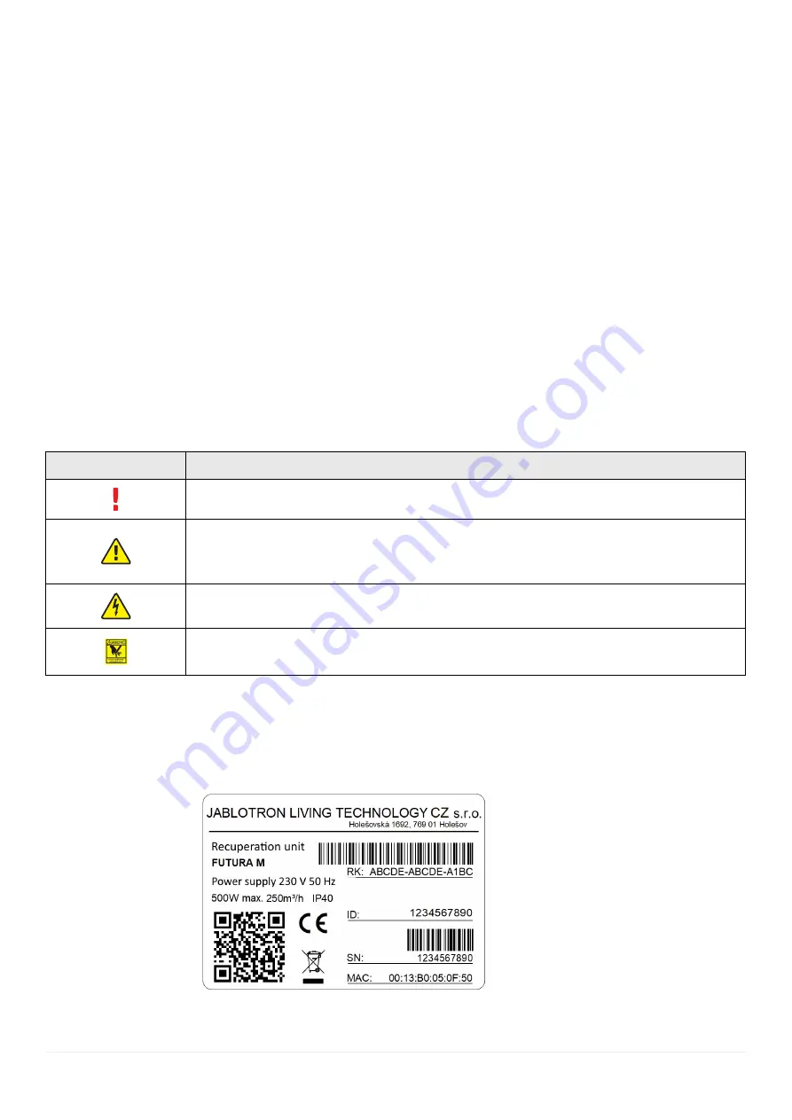
Figure 1 – Identification label

Содержание Futura

Страница 1: ......

Страница 2: ......

Страница 3: ...gency shutdown function 12 Error alerts and their solutions 1 Alfa control panel error alerts 2 Wall mounted control panel error alerts 3 Reset to default settings 13 Maintenance 14 Annex 1 Annex 1 Un...

Страница 4: ...lies with the Commission Regulation EU No 1253 2014 with regard to ecodesign requirements for ventilation units and Commission Delegated Regulation EU No 1254 2014 with regard to energy labelling of r...

Страница 5: ...anical damage and harmful environmental effects and not interfere with the use of the premises where the unit will be installed The unit may be operated only by physically and mentally apt persons tha...

Страница 6: ...ctional Drive type variable speed drive variable speed drive Heat recovery system type recuperative recuperative Heat recovery efficiency 91 8 91 4 Reference flow 175 m h 103 CFM 245 m h 144 CFM Elect...

Страница 7: ...tion which supports easy control of all user functions and settings It enables remote monitoring system administration and provides automatic alerts for error conditions and dirty filter replacement S...

Страница 8: ...llation please allow additional 70 cm 28 in of free space above the unit The following has to be available at the installation site 2 x EPP air duct connections for outdoor use and 2 x Sonotex flexi s...

Страница 9: ...intake from the exterior and the air exhaust to the exterior to prevent the possibility of unwanted condensation inside the pipes For indoor air distribution use Sonotex piping with silencer The air...

Страница 10: ...ds the siphon The condensate drain connection is found on the bottom of the heat recovery unit A siphon which is connected to the sewerage system must be mounted onto the coupling of the condensate dr...

Страница 11: ...ing device must be connected in accordance with relevant standards and guidelines and may only be carried out by a trained service technician with appropriate electrical and refrigeration qualificatio...

Страница 12: ...cts correct directional insertion of filters condensate drain functionality correct electrical connection and readiness for the operation of all technical components of the unit Any defects must be co...

Страница 13: ...ure Short press filter initialization long press Bluetooth connection MyCOMPANY application retrieves serial number from the unit Configuration is saved directly in the unit X2 X3 X4 X5 X6 T1 G N D X1...

Страница 14: ...Continue Figure 8 Ventilation connection check Configuring IP address Configuration of the IP address is run automatically from the DHCP server but may be set manually as well In order to configure th...

Страница 15: ...l air volume and tap on the arrow in the bottom right corner to run the analysis The function will calculate maximum available air flow for each of the five ventilation levels according to the real la...

Страница 16: ...tering the unit must be connected to the internet When the unit is on it logs into the preset server and maintains a permanent connection Figure 16 Registration key Log in to MyCOMPANY run device regi...

Страница 17: ...oning system Max 8 1 1 4 Max 8 1 4 0 2 Figure 20 Possible zone combinations The picture above shows the number of control panels valves and buttons that can be used for each zone When configuring zone...

Страница 18: ...or set the switch to the ON position when you are using a terminating resistor Figure 21 Setting zone number on Alfa control panel DIP switch 8 2 Configuration of a valve DIP switch Second it is neces...

Страница 19: ...me and turn off automatically This configuration can be used for example in a bathroom If the no 5 switch on the DIP is set to the ON position the extract button will work as a switch when pressed the...

Страница 20: ...how how to set valve addresses switches no 4 and 5 and supply zone switch no 6 on a valve DIP switch 5 Figure 24 Example of configuring a supply zone zone no 5 two valves supply 8 5 Extract zone confi...

Страница 21: ...responding zone shown zone no 1 same as in Fig 25 First column switch no 4 shows button address Second column switch no 5 shows that the button is set as a switch ON until pressed again Third column s...

Страница 22: ...ar dependence starting at 1 V see Fig 29 This setting however will not stop the system entirely The minimum power level at 0 V of input voltage corresponds to 1 of the power which is about 65 m h for...

Страница 23: ...operational information is displayed on the control panel start of heating within the heating circuit temperature setpoint of the heating circuit the set heating mode manual mode time schedule vacati...

Страница 24: ...assigned to the selected input see pictures below No additional configuration is needed for the Emergency shutdown input Activation of the function disconnects the contact When the emergency shutdown...

Страница 25: ...door temperature below limit 8 VAV ventilation not configured properly supply Check the setting of the supply zones of the VAV ventilation 9 VAV ventilation not configured properly extract Check the s...

Страница 26: ...error Change sensor Error No 2 Fan error Check cable connection Error No 3 Heat exchanger error Check cable connection Error No 4 I O board error Change I O board Error No 5 9 Unspecified 12 3 Reset...

Страница 27: ...status remove front cover 2 screw dismount filter plugs and remove them remove plugs A B C D with a spatula of minimal width of 5 cm 2 in check the heat exchanger visually clean first half of valve r...

Страница 28: ...aste air C Supplied air D Extracted air Description 1 Outdoor air filter 2 Terminal 3 Main board 4 Servo bypass 5 T RH waste air sensor 6 Circulation servo 7 T RH outdoor air sensor 8 IO board 9 Extra...

Страница 29: ...Technical parameters Insulation thickness 25 mm 1 in R 0 65 m K W Minimal temperature 30 C 22 F Maximum temperature 140 C 284 F Operating pressure 188 to 2500 Pa Operating speed max 25 m s Bend radius...

Страница 30: ...JABLOTRON FUTURA INSTALLATION MANUAL 28 43 JABLOTRON LIVING TECHNOLOGY 14 3 Annex 3 Wiring diagram 3a Internal wiring diagram of Futura...

Страница 31: ...MANUAL 29 43 JABLOTRON LIVING TECHNOLOGY 1 Power supply 24 V 2 Heat exchanger 3 Supply fan 4 Extract fan 5 Drying servo 6 Outdoor air sensor 7 Bypass servo 8 Waste air sensor 9 Fresh air sensor 10 Ex...

Страница 32: ...N FUTURA INSTALLATION MANUAL 30 43 JABLOTRON LIVING TECHNOLOGY In Out 230 V AC 5 4 2 3 1 3b CoolBreeze wiring diagram 1 Outdoor unit 2 CoolBreeze 3 T RH extract air sensor 4 Evaporator 5 NTC evaporato...

Страница 33: ...put connection LED output for LED boost indication 24 V 20 mA max BST boost button IN2 IN1 analog input 0 10V or digital input for potential free contact against GND GND common ground X6 AA bus connec...

Страница 34: ...control panel 1 8 pieces 2 VarioBreeze room by room ventilation button 1 16 pieces 3 CO2 sensor 1 8 pieces 4 VarioBreeze room by room ventilation valve 1 64 pieces 5 NTC outdoor temperature sensor 6...

Страница 35: ...tivated by connecting the contact Example of analog input connection for emergency shutdown Mode is activated by disconnecting the contact Connecting the contact deactivates the mode Example of 0 10 V...

Страница 36: ...simultaneously as this will cause irreparable damage to the system 14 6 1 Connecting Alfa control panel via RS 485 bus ALFA I N O U T 14 6 2 Connecting Alfa control panel via AA BUS Only one control...

Страница 37: ...35 43 JABLOTRON LIVING TECHNOLOGY 14 7 Annex 7 Configuration of control panel and CO2 sensor Modbus RTU addresses 14 7 1 Alfa control panel 1 2 3 OFF 1 ON 2 3 OFF 2 ON 1 3 OFF 1 2 ON 3 OFF 3 ON 1 2 OF...

Страница 38: ...unted control panel with CO2 sensor or a separate CO2 sensor Make sure to always activate via DIP switch a terminating resistor to the last device control panel or sensor in the line Always activate t...

Страница 39: ...of control panel DIP switches CO2 sensor DIP switches and valve DIP switches for max 8 ventilation zones Control panel and CO2 DIP switch combinations are stated in columns 2 4 Valve DIP switch settin...

Страница 40: ...ches and boost button DIP switches for max 8 ventilation zones Valve DIP switch combinations are stated in columns 2 5 according to the actual number of valves within the given zone Boost button DIP s...

Страница 41: ...erence flow rate 175 m h 245 m h Reference pressure difference 50 Pa 50 Pa SPI 0 34 W m h 0 33 W m h Declared maximum internal and external leakage rates 2 5 2 5 2 5 2 5 Position and description of vi...

Страница 42: ...ING TECHNOLOGY 14 10 Annex 10 Energy labels 2017 1254 2014 46 dB I II 3 JABLOTRON LIVING TECHNOLOGY CZ s r o Futura A A B C D E F G A 250 m h 2017 1254 2014 46 dB I II 350 m3 h JABLOTRON LIVING TECHNO...

Страница 43: ...TALLATION MANUAL 41 43 JABLOTRON LIVING TECHNOLOGY 14 11 Annex 11 Dimensional drawing Main dimensions including CoolBreeze indoor unit 133 3x243 830 910 1274 169 6 73 10 110 370 111 247 364 260 1 2 3...

Страница 44: ...JABLOTRON FUTURA INSTALLATION MANUAL 42 43 JABLOTRON LIVING TECHNOLOGY 200 18 59 444 60 33 524 13 14 15 16 17...

Страница 45: ...space of at least 330 mm distance for fitting EPP elbow 5 Refrigerant inlet outlet for CoolBreeze 6 When installing CoolBreeze use a flange from the Futura unit 7 When installing keep space of at lea...

Страница 46: ......

Страница 47: ......

Страница 48: ......

Отзывы: