


- 35 -
A c t u a t o r s w i t h P o t e n t i o m e t e r
Stecker/Plug 4
extern
external
1
3
2
L
+
L
+
L
+
Eingang/Input
Ausgang/Output
Zu/Close
Auf/Open
intern
internal
1
3
2
Stecker/Plug 4
COM
COM
Power Standard
Potentiometer
3
1
2
Stecker/Plug 3
Zusätzliche Endschalter/Auxiliary limit switches
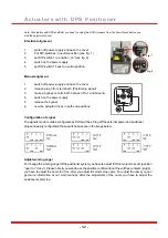
Ansteuerung:
PIN 1 = N/-
PIN 2 = L/+ Close/Zu
PIN 3 = L/+ Open/Auf
PIN 2+3 = Stop
Mounting
The electric actuator must not be operated in manual mode with the hand wheel moving out of its
factory setting/swivel range. It is used a rotating potentiometer. By the gear ratio the zero point will
shift when turning over the working angel. If you have deadjusted the zero point, as long as the
actuator is to twist in the manual mode with 360 ° turns, until the measured value is the same as the
origin value. The potentiometer output signal is an ohmic value which varies in a range between 0 K
Ohm and the specified maximum value. The minimum and maximum value can not be shown,
caused by the design. It is simply a sector. The ohmic values can vary from actuator to actuator, for
the same position. Each actuator is individually to calibrate during installation and put into operation.
For the corresponding positions you can either tap the ascending or descending value of the
potentiometer.
The potentiometer must be specified in the order, as subsequent conversion is not possible.
The electric quarter turn actuator has two adjustable, potential- / volt- free signals for the position
confirmation.
1 KOhm
5 KOhm
10 Kohm
The potentiometer output signal shows the actual position of the valve shafts. The signal is shown in
an ohmic value. This can be evaluated by an appropriate control and then processed. The following
three potentiometer values are available:
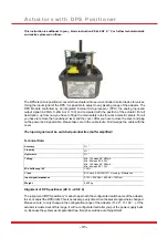
Reference
If it is desired that the actuator stops in intermediate positions without major effort, the model with
positioner DPS is to choose. The model is available in versions 0 - 10 V, 4 - 20 mA or 0 - 20 mA / Input
and output signal.
Содержание J2 L/H 10
Страница 26: ...Jumper Configuration Heater active Optional Configuration Heater inactive 26 Basic configuration...
Страница 28: ...Special Models Series J3 J3C...
Страница 38: ...A p p e n d i x...
Страница 46: ...Dimensional Drawing 4xM6 4xM5 05 36 52 52 6 621 130 51 181 15 7 401 14 46 J2 H L 10...
Страница 47: ...Dimensional Drawing 181 130 51 55 55 42 14 11 9 6 3 5 0 110 110 1 1 3 1 5 1 4xM6 4xM5 4xM5 841 47 J3 S20...
Страница 48: ...14 11 9 130 51 42 55 55 169 110 15 13 11 4xM6 4xM5 4xM5 0 5 6 3 181 Dimensional Drawing 48 J3C S20 35...
Страница 49: ...B MAN A AUTO 110 181 130 51 16 19 55 55 4xM8 4xM6 14 17 5 0 7 0 691 Dimensional Drawing 49 J3C S55...
Страница 50: ...16 19 130 51 55 55 691 1 7 6 011 14 17 4xM8 4xM6 0 5 0 7 1 8 1 Dimensional Drawing 50 J3C S85...
Страница 52: ...Te l 4 9 5 1 8 1 6 0 1 7 i n f o j u j d e u t s c h l a n d d e w w w j u j d e u t s c h l a n d d e...


