Appendix D: Configuration Examples
58 (62)
D
Configuration Examples
D.1
Example 1: Connecting a CAN Network With a Computer
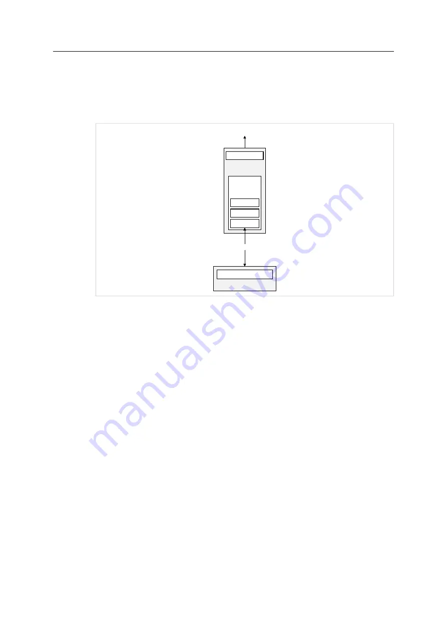
The example shows how an installed virtual COM port can be used to configure the CANblue II
to exchange data with a CAN network connected to the CANblue II.
Fig. 12
PC Interface
The following specifications apply in the example:
•
CAN network is operated at data rate of 500 kBaud.
•
Exclusively the following messages are forwarded by the CANblue II:
–
data and remote frames with Standard identifier 5
–
remote frames with Standard identifier 1F
–
data frames with Extended identifier 1A2B3C
►
Make sure that the virtual COM port is installed.
►
Make sure that the software package (
CANblue_II_Generic_Setup.exe
) is installed.
►
Start the terminal program or the CANblue Configuration Tool (
CANblueCon.exe
).
►
Reset the device to factory settings with command
D SETTINGS_DEFAULT
.
►
Initialize the CAN controller to 500 kBaud with command
C CAN_INIT 500
.
►
To set the filter, use the following commands:
–
C FILTER_ADD 5
–
C FILTER_ADD STD 5 RTR
–
C FILTER_ADD STD 1F
–
C FILTER_ADD EXT 1A2B3C
►
Activate the Standard filter with command
C FILTER_ENABLE STD
.
►
Activate the Extended filter with command
C FILTER_ENABLE EXT
.
►
Check the configuration with command
C CONFIG SHOW
.
CANblue II
CAN connector
Bluetooth
connection
(SPP-Server)
CAN bus 1
PC
Bluetooth
Config
Slave
Master
Bluetooth connection
CANblue II User Manual
4.01.0126.20000 EN 3.2


