iXsystems FreeNAS Mini Скачать руководство пользователя страница 25

23

CONCLUSION

Reconnect the external cables and power on the FreeNAS system.  The 
network card upgrade is now complete.

ADDITIONAL RESOURCES

The FreeNAS Mini and Mini XL support many features and configurations 

not mentioned in this Network Card Upgrade Guide.

For help upgrading hardware, refer to the FreeNAS Mini and Mini XL 
Hardware Upgrade Guide: 

https://www.iXsystems.com/FreeNAS_Mini_HW_

Upgrade.pdf

.

For help replacing the Mini and Mini XL Motherboard, refer to the FreeNAS 
Mini Motherboard Replacement Guide: 

http://iXsystems.com/FreeNAS_

Mini_Motherboard_Replacement.pdf

.

For complete documentation: 

http://doc.freenas.org

.

The FreeNAS Forums provide an opportunity to interact with other  

FreeNAS users and to discuss their configurations.  Visit the forums: 


http://forums.freenas.org

.

Содержание FreeNAS Mini

Страница 1: ...FreeNAS Mini and Mini XL Network Upgrade Kit June 2017 Edition For more information about the FreeNAS Mini product line and a digital download of this guide visit www iXsystems com freenas mini...

Страница 2: ...l 9 Motherboard Tray Removal 10 Slot Cover Removal 11 Part II Installation of Cables and Components 12 Network Card Installation 12 Motherboard Tray Installation 14 SATA Cable Connection 15 Power Supp...

Страница 3: ...he kit includes either one Chelsio 10Gb Network Interface Card with dual SFP ports or one Intel 10Gb dual port network card with RJ45 connectors SFP modules can be ordered separately or may be include...

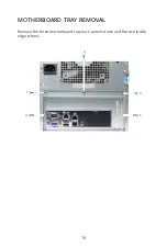
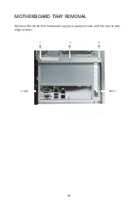
Страница 4: ...2 FREENAS MINI Motherboard Tray PCIe Slot PARTS LOCATION FREENAS MINI XL Motherboard Tray PCIe Slot...

Страница 5: ...If a Tamper Resistant sticker is present removing or cutting it to remove the case will not affect the warranty on the unit NETWORK CARD BRACKETS The FreeNAS Mini uses a short half height bracket and...

Страница 6: ...T ADAPTER SFP The Chelsio 10Gb network card connects the Mini or Mini XL directly to a fiber optic network via the PCIe slot on the motherboard This card supports SFP modules which may not be included...

Страница 7: ...ADAPTER WITH RJ45 CONNECTORS The Intel 10Gb Adapter uses standard Cat 6 cabling with two RJ45 copper connectors to connect the Mini or Mini XL to the network via the PCIe slot This card does not supp...

Страница 8: ...pes of SFP modules are available and connecting them to the network depends on the type Note The Intel network card does not support SFP modules The SFP module has a rubber dust cover Keep the cover i...

Страница 9: ...AND COMPONENTS Some cables and components must be disconnected or removed before the network card can be installed OPENING THE FREENAS MINI CASE Unscrew the four thumbscrews on the rear of the Mini 1...

Страница 10: ...th a 24 pin connector Press in on the upper part of the latch and pull the connector upward to disconnect the power supply cable Note Force may be needed as the connector is tight It helps to hold the...

Страница 11: ...Remove the four SATA cables connected to the blue SATA connectors and any optional SATA cables connected to the white slots Remove each connector individually by gently pulling upwards on the black p...

Страница 12: ...10 MOTHERBOARD TRAY REMOVAL Remove the three motherboard tray back panel screws and the two inside edge screws 4 5 1 3 2...

Страница 13: ...11 SLOT COVER REMOVAL Gently lift and slide the motherboard tray out of the chassis Remove the slot cover screw and slot cover from the back panel Save the screw...

Страница 14: ...K CARD INSTALLATION Slide the motherboard tray out of the chassis until there is enough room for the network card to fit into the PCIe slot Align the network card with the PCIe slot and press down on...

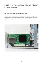
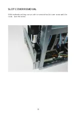
Страница 15: ...13 Use the slot cover screw removed earlier to attach the new network card to the back panel...

Страница 16: ...14 MOTHERBOARD TRAY INSTALLATION Slide the motherboard tray gently back into place Replace the three motherboard tray back panel screws and the two inside edge screws 4 5 1 3 2...

Страница 17: ...he drive bay to the blue motherboard SATA ports There are two SATA cables for optional SSD cache drives If present the SSD cache drives are installed on the top or side of the drive cage If not presen...

Страница 18: ...ly connector Press down firmly with both hands until fully seated and latch is closed CLOSING THE FREENAS MINI CASE Replacing the case is the opposite of removal Slide the case back on being careful n...

Страница 19: ...WORK CARD INSTALLATION PART I REMOVING COMPONENTS OPENING THE FREENAS MINI XL CASE The right side panel must be removed Unscrew the two thumbscrews on the back of the right panel then slide the panel...

Страница 20: ...18 MOTHERBOARD TRAY REMOVAL Remove the three motherboard tray back panel screws and the two inside edge screws 4 5 2 1 3...

Страница 21: ...19 SLOT COVER REMOVAL Slide motherboard tray out an inch to remove the slot cover screw and slot cover Save the screw...

Страница 22: ...S NETWORK INTERFACE CARD INSTALLATION Place the network card into the Mini XL from the side Position the bracket over the back panel and the card over the PCIe slot Press down on the ends of the card...

Страница 23: ...21 Use the slot cover screw removed earlier to attach the new network card to the back panel...

Страница 24: ...de that hook onto the chassis Align the metal tabs with the chassis and guide the panel towards the front of the system until it slides into place Placing the Mini XL on its side with a towel undernea...

Страница 25: ...efer to the FreeNAS Mini and Mini XL Hardware Upgrade Guide https www iXsystems com FreeNAS_Mini_HW_ Upgrade pdf For help replacing the Mini and Mini XL Motherboard refer to the FreeNAS Mini Motherboa...

Страница 26: ...Copyright 2017 iXsystems FreeNAS is a registered trademark of iXsystems Inc All rights reserved All other registered trademarks trademarks are property of their respective owners...

Отзывы: