HDC/HDR_UM_9752092810_NL_D_GB_F_V2_1
16
Warning:
Do not route high voltage cables next to any sharp metal components and take care to
avoid sharp bends and kinks in the cable.
Keep high-voltage cables separated from low-voltage wiring.
Metal parts near the charging bars, including the machine frame, must be earthed.
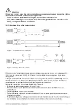
5.2.3. Assembly of high voltage plug
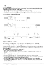
Figure 1: 30 kV and 60 kV HV connectors
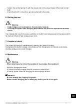
Figure 2: Assembly of HV connectors
Depending on the high voltage power unit used, a 30 kV HV connector or a 60 kV HV
connector (Figure 1) is fitted to the charging bar connection cable.
If a high voltage cable with a protective sleeve (standard) is used, the knurled screw supplied
with the HV connector is not required. The knurled screw is replaced by the gland fitted to the
protective sleeve.
Fit the HV connector in accordance with Figure 2.
- Strip 25 mm of the high voltage cable (2).
- Bend the stripped cores of the high voltage cable back on themselves. Do not twist the
cores.
- Slide the pipe (1) over the cable.
- Slide the metal contact bush (3) over the cable until it abuts the cable insulation.
- Slide the pipe back over the contact bush so that the screw hole in the contact bush and the
cores of the cable are visible through the hole in the pipe.
- Screw the set screw (4) through the pipe in the metal contact bush so that the unit is
securely attached to the cable. The set screw must be at the same height as or below the
surface of the pipe.


