5
A
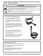
a. Cover Removal and Installation Procedure
For FS1 models with NEMA 1 Enclosure
• Using a flathead screwdriver, loosen but do not
remove the two cover screws and remove the
cover (A).
• Place the cover on the flow switch sliding the slots
behind the two loose cover screws. Push the cover
down into the flow switch and using a flat blade
screwdriver, tighten the cover screws to a torque of
10 lb•in (1.13 N•m).
For FS1-W models with NEMA 4X Enclosure
• Using flathead screwdriver, unscrew the six cover
screws and remove cover.
• Place the electrical connection cover on the flow
switch and insert the six cover screws. Tighten the
screws to a torque of 10 lb•in (1.13 N•m).
STEP 3 - Electrical Installation
• To prevent electrical shock, turn off the electrical power before making electrical connections.
• To prevent an electrical fire or equipment damage, electrical wiring insulation must have a rating of
167˚F (75˚C) if the liquid’s temperature exceeds 180˚F (82˚C).
• To prevent electrocution, when the electrical power is connected to the flow switch, do not touch the
terminals.
• Make sure flow switch electrical cover is secured before turning on electric power.
Failure to follow this warning could cause property damage, personal injury or death.
!
WARNING
b. Electrical Conduit Connection
• Connect electric conduit to flow switch electrical enclosure.
• Follow accepted electrical practices when installing fittings
and making connections.
• Refer to and follow local codes and standards when
selecting the types of electrical fittings and conduit to
connect to flow switch.
Содержание McDonnell & Miller FS1 Series
Страница 8: ......


