background image

3. Tighten the bonnet fasteners in a crisscross pattern.

For more information, see Fastener torque table for valve body to topworks in this manual.

4. Make multiple crisscross passes to build up torque to the final table value. Make additional crisscross

passes using final table values to evenly tighten each fastener to within 5% of  torque value.

5. Retighten the bonnet fasteners as noted above at ambient conditions after the system has cycled

through operating pressure and temperature.

6. Monitor the valve for leakage:

If  leakage ...

Then ...

Occurs at the body/bonnet

flange sealing area

Depressurize the system and retighten the bonnet fasteners as

noted above.

Continues

Depressurize the system and retighten the bonnet fasteners as

noted above. (maximum 3rd re-torque)

Continues

Replace the valve diaphragm.

For more information, see Replace the valve diaphragm in this manual.

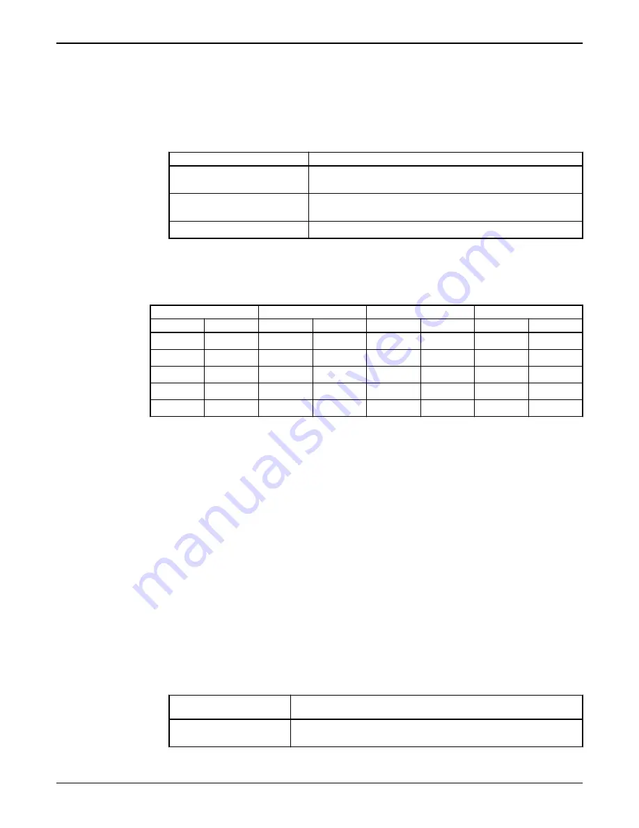
Fastener torque table for valve body to topworks

Values given are for lubricated fasteners.

Valve size

Bolt size

PTFE diaphragm

Elastomer diaphragm

Inch

DN

Imperial

Metric

in-lb

N-m

in-lb

N-m

0.50

15

1/4"

M6

25-60

2.8-6.8

20-40

2.3-4.5

0.75

20

1/4"

M6

50-65

5.7-9.1

20-50

2.3-5.7

1.00

25

5/16"

M8

65-90

7.4-11.3

45-70

5.1-7.9

1.50

40

3/8"

M10

200-225

23-25

75-130

8.5-14.7

2.00

50

7/16"

M12

225-275

25-31

100-180

11-20

Guidelines

• Minimum values given will provide a longer diaphragm cycle life for valves in non-autoclave and low

thermal cycle conditions.

• Maximum values given may be necessary for autoclave conditions and for high thermal cycle

conditions.

• Torques should be applied at near ambient conditions (less than 100ºF (38ºC)).

Disassemble the valve

1. Remove all line pressure.
2. Do you have a switch package?

• If  yes: Proceed to step 3.
• If  no: Proceed to step 5.

3. Do you have a fail open or double acting actuator?

• If  yes: Proceed to step 4.
• If  no: Proceed to step 5.

4. Do you have a series 33 actuator or adjustable opening stop?

• If  yes: Remove the switch package.
• If  no: Proceed to step 5.

5. If  the actuator mode of  operation is fail open or fail close, then load the actuator with air.

If  the actuator mode of

operation is ...

Then ...

Fail open

Load the air port in the upper cover of  the actuator with sufficient air

to partially close the valve.

Maintenance

8

Advantage

®

 Actuator 2.0 Maintenance Manual

Содержание Advantage Actuator 2.0

Страница 1: ...Industrial Process Maintenance Manual Advantage Actuator 2 0...

Страница 2: ......

Страница 3: ...Adjust the travel closing stop 12 Replace the spindle o rings 12 Lubrication requirements 12 Replace the actuator diaphragm and spring for fail open actuator 13 Replace the actuator diaphragm and spr...

Страница 4: ...ecommended by an ITT engineer WARNING Misapplication of the valve can result in injury or property damage Select valves and valve components of the proper materials and make sure that they are consist...

Страница 5: ...ication marks associated with the product Maintenance safety precautions Be aware of these safety precautions when performing maintenance on this product You must decontaminate the product if it has b...

Страница 6: ...efining the actuator as follows Table 1 Actuator Code Description B Advantage actuator 2 0 Table 2 Mode of operation Code Description 1 Fail open spring to open air to close direct acting 2 Fail close...

Страница 7: ...aled bonnet The non sealed bonnet has a weep hole that permits leakage of the process fluid if the diaphragm ruptures Sealed bonnet The sealed bonnet uses a special V notch vent plug which permits dia...

Страница 8: ...the diaphragm tabs The molding date grade of diaphragm and valve size provide traceability to original batch records Supplier code Date code Figure 4 Elastomer diaphragm front Grade of diaphragm Valve...

Страница 9: ...from the plug Replace the valve diaphragm Sealed bonnet Fluid weeping from the plug Loosen the v notch vent plug 2 3 turns to check Replace the valve diaphragm Actuator s bonnet weep hole and air por...

Страница 10: ...erial Metric in lb N m in lb N m 0 50 15 1 4 M6 25 60 2 8 6 8 20 40 2 3 4 5 0 75 20 1 4 M6 50 65 5 7 9 1 20 50 2 3 5 7 1 00 25 5 16 M8 65 90 7 4 11 3 45 70 5 1 7 9 1 50 40 3 8 M10 200 225 23 25 75 130...

Страница 11: ...formation see Disassemble the valve in this manual 2 If the actuator mode of operation is fail open pressurize the actuator by applying air to the upper cover slightly extending the compressor and dia...

Страница 12: ...ng cushion from rotating 7 Rotate the diaphragm until hard stop or heavy resistance is achieved and additional force does not significantly rotate the diaphragm into the compressor 8 If replacing a PT...

Страница 13: ...ply excessive air pressure that results in inversion of the diaphragm 11 Replace the topworks assembly on the body and tighten the bonnet fasteners For more information see Tighten the bonnet fastener...

Страница 14: ...ve in this manual 4 Disassemble the actuator For more information see Replace the actuator diaphragm and spring for proper mode of operation fail open fail close or double acting in this manual 5 With...

Страница 15: ...in the fixture lower plate d Place the support plate and spacer plate on the actuator top plate e Turn the fixture handwheel clockwise to remove the load from the indicator spindle f Remove the spind...

Страница 16: ...24 UNC tapped hole former plug location c Turn the fixture handwheel clockwise until the stem rests on the actuator top cover d Remove all the cover to cover caps fasteners and washers e Turn the fixt...

Страница 17: ...he spindle nut surface with Loctite 7649 Primer N b Apply Blue Loctite 242 to the indicating spindle c Replace the indicating spindle 9 Assemble the upper cover using care to keep the air fitting in l...

Страница 18: ...6 parts List of parts 11 12 1 8 NPT 10 3 9 7 2 4 5 1 6 Figure 7 Fail open and double acting actuator 15 16 17 13 18 NPT 14 Figure 8 Low profile actuator 8 1 8 NPT Figure 9 Fail close actuator Parts Li...

Страница 19: ...less Steel Cast Iron Zinc or Bronze 1 113 Diaphragm As required 1 123 Backing Cushion EPDM 1 133 O Ring FKM 1 14 Lower Actuator Cover Plastic 1 15 Bonnet Stainless Steel 1 163 O Ring FKM 2 17 Bushing...

Страница 20: ...Outer Column 4 126 Spacer 1 13 Spring Pin 1 14 Lower Plate 1 15 Rod 1 16 Machine Screw 4 17 Shim Washer As required 18 Spacer Plate 1 197 Cap Screw 2 207 Bar 1 217 Inner Column 2 227 Support Plate 1...

Страница 21: ......

Страница 22: ...ancaster PA 17603 USA Tel 717 509 2200 Fax 717 509 2316 E mail pureflo custserv itt com Richards Street Kirkham Lancashire PR4 2HU England Tel 44 1772 682696 Fax 44 1772 686006 2009 ITT Corporation Th...

Отзывы: