Itm Trademaster WE-350DSA Скачать руководство пользователя страница 12

- 11 - 

- Parts with a thin and/or variable section such as 

profiles, pipes and plate, fine toothing is needed, so 
that the number of teeth used simultaneously while 
cutting is from 3 to 6; 

- Parts with large transverse sections and solid 

sections need widely spaced toothing to allow for the 
greater volume of the shavings and better tooth 
penetration; 

- Parts made of soft material or plastic (light alloys, 

mild bronze, Teflon, wood, etc.) also require widely 
spaced toothing; 

- Pieces cut in bundles require combo tooth design. 

 
8.3 Teeth pitch 

As


already


stated,


this


depends


on


the


following


factors: 

-


Hardness of the material 

-


Dimensions of the section


-


Wall thickness.


8.4 Cutting and advance speed


The


cutting


speed


(m/min)


and


the


advance


speed


(cm

2

/min


=area


traveled


by


the


disk


teeth


when


removing


shavings)


are limited


by


the


development


of


heat


close


to


the


tips


of


the


teeth. 

- The


cutting


speed


is


subordinate


to


the


resistance


of


the


material


(R


= N/mm

2

),


to


its


hardness


(HRC)


and


to


the


dimensions


of


the


widest


section. 

- Too


high


an


advance


speed


(=


lowering


of


the


saw


frame) tends


to


cause


the


disk


to


deviate


from


the


ideal


cutting


path, producing


non


rectilinear


cuts


on


bath


the


vertical


and


the horizontal


plane. 

 
The


best


combination


of


these


two


parameters


can


be


seen directly


examining


the


chips. 

 
Long


spiral-shaped


chips


indicate


ideal cutting. 

 
Very


fine


or


pulverized


chips


indicate


lack of


feed


and/or


cutting


pressure

 
Thick


and/or


blue


chips


indicate


overload of


the


blade. 


8.5 Blade running-in 
When cutting for the first time, it is good practice 
to run in the tool making a series of cuts at a low 
advance speed 

(=


30-35


cm

2

/min


on


material


of


average


dimensions


with


respect


to


the


cutting


capacity


and


solid


section


of


normal


steel with


R = 

410-510


Nimm

2

). 

  Generously spraying the cutting 

area with lubricating coolant.


8.6 Blade structure


Bi-metal


blades


are


the


most


commonly


used.


They


consist


of


a silicon-steel


blade


backing


by a


laser


welded high


speed


steel


(HHS)


cutting


edge.


The


type


of


stocks


are classified


in


M2,


M42,


M51


and


differ


from


each


other


because of


their


major


hardness


due


to


the


increasing


percentage


of Cobalt


(Cc)


and


molybdenum


(Mo)


contained


in


the


metal


alloy. 

 
8.7 Blade type 

They


differ


essentially


in


their


constructive


characteristics,


such as: 

Shape 

and


cutting

 angle 

of


tooth 

-

 Pitch 

Set


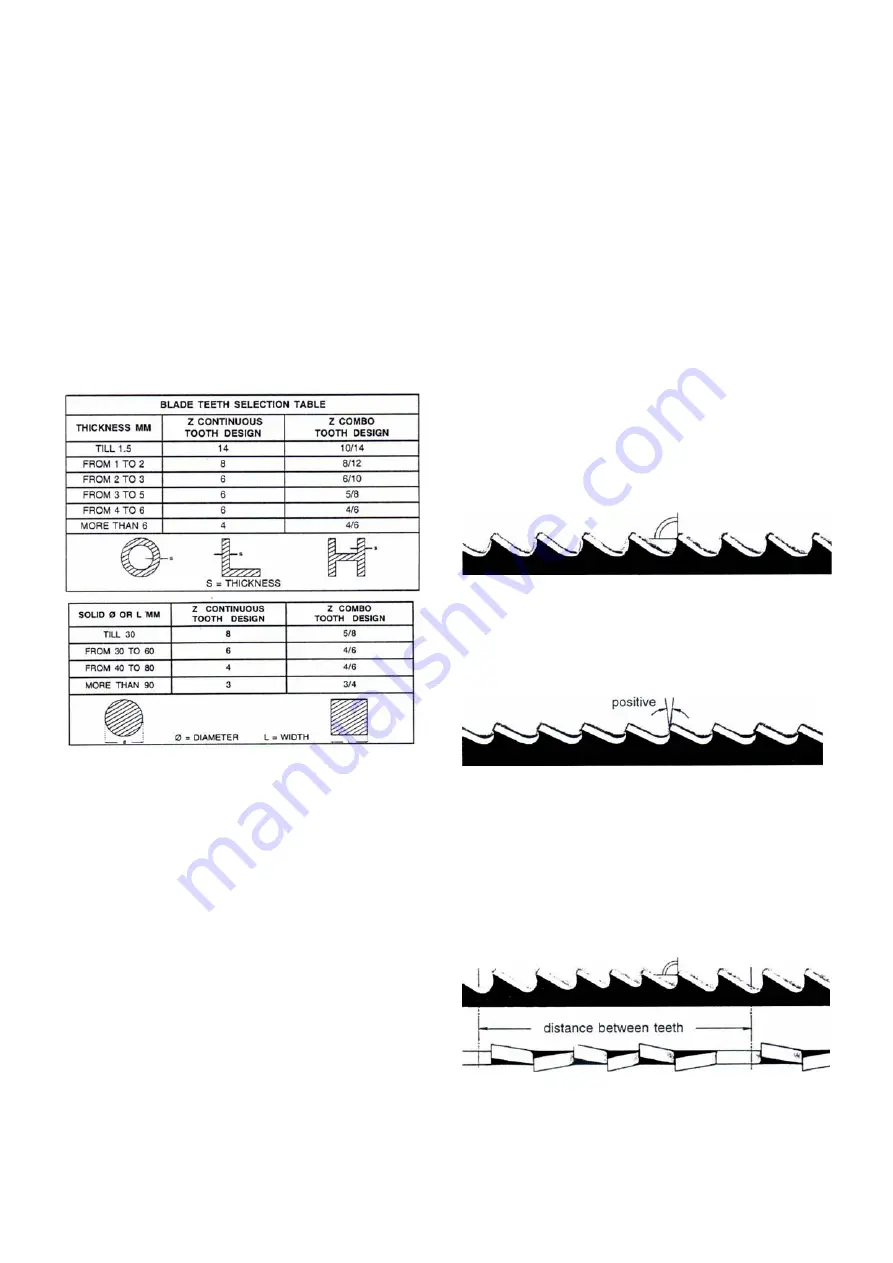
Shape and angle of tooth


REGULAR TOOTH: 


rake


and


constant


pitch.   


Most


common


form


for


transversal


or


inclined


cutting


of


solid small


and


average


cross-sections


or


pipes,


in


laminated


mild steel


and


gray


iron


or


general


metal. 

 
POSITIVE


RAKE


TOOTH:


- 10º


positive


rake


and


constant pitch. 


Particular


use


for


crosswise


or


inclined


cuts


in


solid


sections


or large


pipes,


but


above


all


harder


materials


(highly


alloyed


and stainless


steels,


special


bronze


and


forge


pig iron). 

 
COMBO


TOOTH:


pitch


varies


between


teeth


and


consequently varying


teeth


size


and


varying


gullet


depths.


Pitch


varies


between


teeth,


which


ensures


smoother,


quieter


cut


and


longer blade


life


owing


to


the


lack


of


vibration.  


Another


advantage


offered


in


the


use


of


this


type


of


blade


in


the fact


that


with


an


only


blade


it


is


possible


to


cut


a wide


range


of different materials


in


size


and


type. 

 
COMBO


TOOTH:


- 10º


positive


rake. 

Содержание Trademaster WE-350DSA

Страница 1: ......

Страница 2: ...JUSTING YOUR MACHINE 5 1 Blade tension assembly 7 5 2 Adjusting the blade guide 7 5 3 Changing the blade 7 5 4 Saw frame return stroke limiting device 7 Chapter 6 ROUTINE AND SPECIAL MAINTENANCE 6 1 D...

Страница 3: ...n as possible All internal operations maintenance or repairs must be performed in a well lit area or where there is sufficient light from extra sources so as to avoid the risk of even slight accidents...

Страница 4: ...over the machine 2 7 Dismantling due to deterioration and or obsolescence General rules If the machine is to be permanently demolished and or scrapped divide the material to be disposed of according t...

Страница 5: ...ator light 16 Foot pad s emergency button indicator light 17 Foot pad operation indicator light 3 3 Vice adjustment Clamping the Work Piece Place work piece between the jaws Use the hand wheel to clos...

Страница 6: ...flow control fails to activate then switch C D and F cannot operate Indicator light 7 will blink if any are pressed indicating that start switch G has failed to activate Check the hydraulic oil level...

Страница 7: ...ght 15 indicates the hydraulic motor has overloaded 6 Indicator light 11 indicates the speed is not properly selected If the saw bow up down switches are out of order then indicator lights 2 and 3 wil...

Страница 8: ...ust accordingly BEFORE PERFORMING THE FOLLOWING OPERATIONS THE ELECTRIC POWER SUPPLY AND THE POWER CABLE MUST BE COMPLETELY DISCONNECTED 5 3 Changing the blade To change the blade Lift the saw arm Loo...

Страница 9: ...ting device Replace the spring by loosening the upper coupling rod and releasing it from the lower tie rod 6 ROUTINE AND SPECIAL MAINTENANCE THE MAINTENANCE JOBS ARE LISTED BELOW DIVIDED INTO DAILY WE...

Страница 10: ...g the 2 set screws Use a vacuum cleaner to vacuum chips and debris from the tank Replace the drain plug Thoroughly clean the pump P and replace Fill tank with coolant to a level about 25mm below the f...

Страница 11: ...ion according to practical considerations and common sense so as to achieve an optimum condition that does not require countless operations to prepare the machine when there are many variations in the...

Страница 12: ...ng for the first time it is good practice to run in the tool making a series of cuts at a low advance speed 30 35 cm 2 min on material of average dimensions with respect to the cutting capacity and so...

Страница 13: ...thin section bars from 1 to 3 mm ALTERNATE SET IN GROUPS Groups of cutting teeth right and left alternated by a straight tooth This set is associated with very fine teeth and it is used for extremely...

Страница 14: ...13 10 WIRING DIAGRAMS...

Страница 15: ...14...

Страница 16: ...dition c Check the connection points of the safety limit switches at their locations on the machine for normal condition refer to the wire diagram No WT M3 C 01 connection wire No 4 5 6 7 8 19 and 20...

Страница 17: ...ers and see if both are properly located and closed b Check the limit switches for normal condition Check the connection for wire No 61 and 68 10 Motor M1 M2 Over loaded indicator light blinking a Che...

Страница 18: ...heck for clogging of coolant drain holes on the blade guide blocks and that flow is plentiful in order to facilitate the removal of chips from the blade Material surfaces can be oxidized or covered wi...

Страница 19: ...lf or have hardened areas or inclusions inside the section due to productive agents used such as casting sand welding wastes etc Avoid cutting these materials or perform cutting with extreme care clea...

Страница 20: ...ainst the support due to deformed or poorly welded bands tapered causing cracks and swelling of the back contour Check level of liquid in the tank Increase the flow of lubricating refrigerant checking...

Страница 21: ...quality blade Worn out blade or with chipped and or broken teeth Wrong tooth pitch Blade guide block too far from material to be cut Insufficient lubricating coolant or wrong emulsion Decrease advance...

Страница 22: ...M10 1 23 1 Hose 1 x45cm 1 65 Shaft Nut 1 24A Coolant and Chip Tray 1 65 1 Oil Seal 1 24 1 Plate 4 65 3 Disk 1 24 2 Hex Cap Bolt M10x20 4 65 4 Spring Washer M8 4 24 3 Nut M10 4 65 5 Hex Socket Cap Scr...

Страница 23: ...Hex Socket Cap Screw M12x20 2 117 Hand Wheel 1 174A Limit Switch Plate 1 117 1 Spring Washer M6 1 175 Spring Washer M8 4 117 2 Hex Socket Cap Screw M6x25 1 176 Nut M8 4 117 3 Bushing 1 177 Spring Was...

Страница 24: ...olt M6x12 2 223 Handle Wheel 1 285 Washer M6 2 223 1 Thrust Bearing 51103 1 326A Flow Control 1 223 2 Blade Tension Gauge 1 327A Hose 2 5 meters 1 223 3 Plate 1 328A Hose 2 0 meters 1 224 Special Spri...

Страница 25: ...24...

Страница 26: ...25...

Страница 27: ...26...

Страница 28: ...5 6 2 7 0 2 2 7 3 2 2 7 4 2 2 7 2 1 2 2 7 2 2 7 6 4 2 7 5 2 6 6 8 2 6 5 8 2 6 4 2 2 6 5 1 2 2 6 9 2 2 5 9 2 2 6 1 2 6 0 2 6 8 2 2 6 7 2 2 4 9 1 2 6 2 2 2 6 3 2 2 8 0 2 7 9 2 2 5 0 4 2 4 9 2 5 1 2 2 8...

Страница 29: ...28 327A Semi Auto and Vise Hydraulic System 332A 335A 333A 171 338A 339A Z 334A 337A 1 336A 337A 341A 340A 159 330A 326A 114 c p 328A 332A 329A 331A ADJ Pressure 15 30kg cm Vise pressure ADJ Z _...

Отзывы: