6
If a slide is located on two parallel guide rails, initially the faste-
ning screws of both rails should only be lightly tightened.
The carriage plate is then aligned with all the guide carriages
and screwed to them (M
A
= 5.8 Nm, refer to section ’Setting up
the Guide Carriage’). In order to ensure parallel alignment, this
slide must then be moved a number of times along the rails. To
protect the wipers during this operation, lengths of adhesive
tape must be applied to the upper surfaces of the rails in order
to cover the sharp edges of the holes. Only when both rails
have been aligned in parallel and at the correct angle should
the guide rails be screwed down by applying the tightening
torque specified above, working from the centre of the rail to
both ends; all the holes are then sealed with the plastic plugs.
Installing the Guide Rail
As a result of the internal stresses generated when the guide rails are ground
to shape, a rail in as-supplied condition may not be perfectly straight. However,
this condition will be rectified when the rail is screwed onto the profile groove.
For this reason, it may be advisable to obtain approximate alignment to the
profile groove with a number of screws before the final tightening operation.
The 1,900 mm long guide rails are factory-prepared at both ends to accept the
guide carriage.
If a rail is shortened, it is important to ensure that after it is fastened
down, the carriage can be slid onto the rail at the non-shortened end.
If the guide is installed flush in an enclosing structure, the carriage must be
placed onto the guide rail prior to assembly.
Cut Groove Profile 8 Al to the right length for the guide rail and insert it into
the guide groove provided. The rail is 20 mm longer than Groove Profile 8 Al in
order to allow space for any connecting elements of the connecting structure.
Place the guide rail onto the groove and remove the protective film from the top
of the rail.
Insert the screws, DIN 912 M4x16 Property Class 10.9 (No. 0.0.406.75) into
the holes in the guide rail and tighten them by hand. Avoid tilting the guide rail
and ensure that it is aligned in terms of position and angle.
The recommended maximum tightening torque for these fastening
screws is 4.8 Nm. Build up to this figure by tightening alternate screws
in three stages:
Pass 1: to 2.0 Nm
Pass 2: to 3.5 Nm
Pass 3: to 4.8 Nm
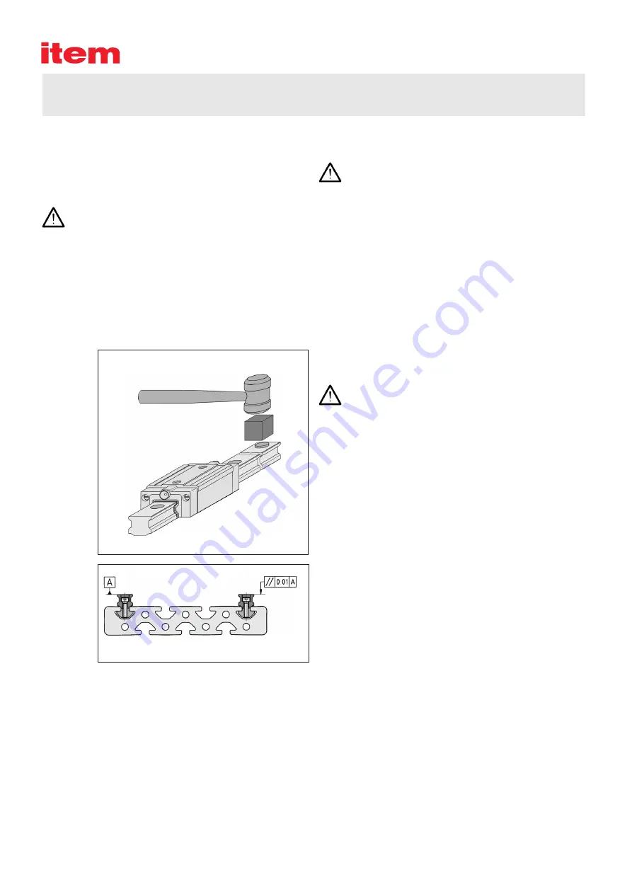
Once the rail has been screwed down, insert the plastic plugs
into the holes and secure them with the aid of a block. Remove
the abraded plastic edge and deburr the hole with an oilstone.
It is not possible to remove the plastic plugs without
irreparably damaging them. If you decide to remove
the guide rail at a later date, the plastic plugs (No.
0.0.443.08) must be replaced before the Linear Guide
System is returned to service. If this is not done, the wi-
pers of the guide carriage will be damaged by running
over the sharp edges of the holes.


