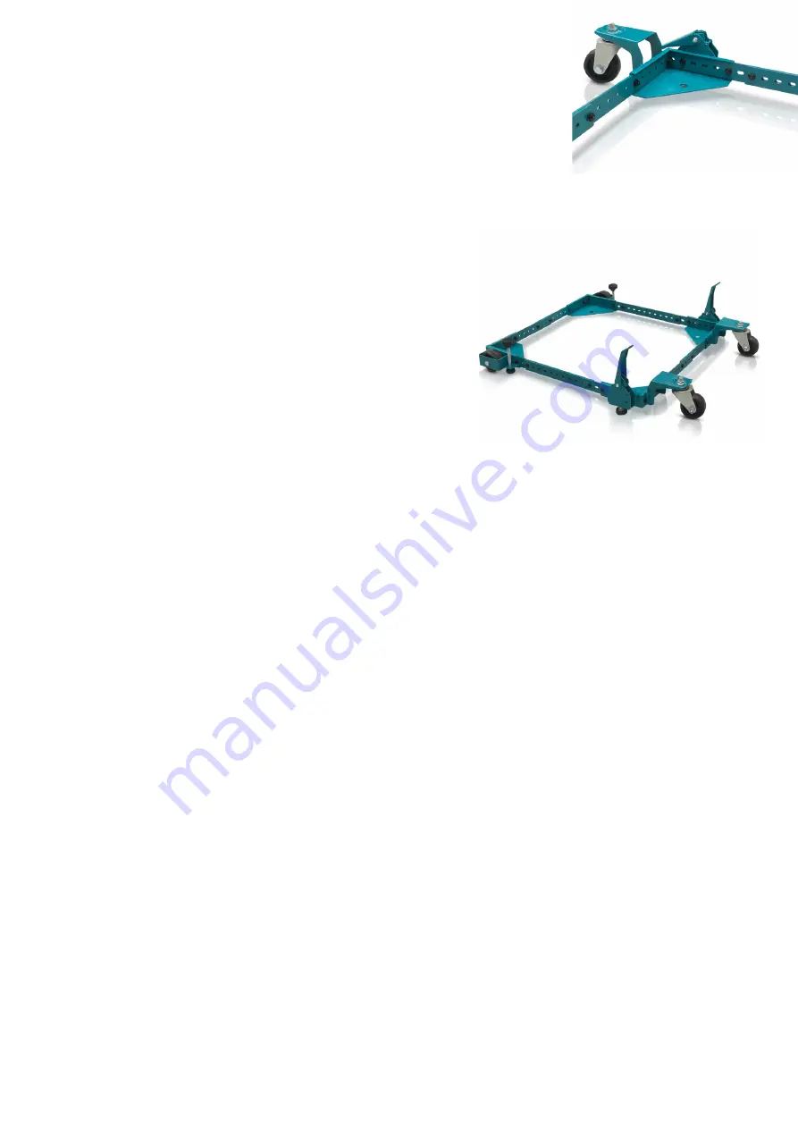
Assembly Examples
Your machine will be stable when down on the floor and when both foot levers
are pressed allowing repositioning. However the stability must be considered
when raising or lowering the machine as when only one foot lever is up and one
foot lever is down the machine will be temporarily unstable due to a corner being
raised higher than the other.
Before ou start consider which configuration would be most suitable for your
machine. As well as stability, also consider whether the position of the foot levers can be a trip hazard.
Choose the configuration which keeps them away from the operators standing / machining zone.
Long Configuration
A long narrow base, such as a Lathe or planer thicknesser, will ben-
efit from this arrangement with both foot levers on one end.
Wide Configuration
A Machine with a short narrow base, such as a Morticer or Band-
saw, will benefit from this arrangement.
The castors are in a wider position which reduces the amount of tilt
during raising and lowering of the foot levers.
Assembly Instructions
Tools Required - 10mm, 11mm, 13mm, 14mm & 16mm Spanners and a Tape Measure.
1) Carefully measure the foot print of the machine you are going to mount and add about 20mm to the dimen-
sion for clearance.
2) Plan the assembly to help you determine the most suitable orientation for the front corner brackets. only you
can determine the best solution for your particular machine requirements for stability.
3) Select and arrange the corners and side rails as necessary to assemble the base to your machines foot-
print.
A short narrow base, such as a Morticer or Bandsaw, will benefit from this arrangement. The castors are in a
wider position which reduces the amount of tilt during raising or lowering of the foot levers.
- From the outside of the Corner bracket (#01 & #02), insert a 50mm long bolt through the bracket, through
the Wheel, through the bush and secure with a thread in bracket.
.
4) Assemble the Castors
Screw in the Rubber Foot (#26) and Locking Nut . Set and lock the height with the nut which should be below
the bracket. The end of the rubber foot should project the same amount below the corner bracket as the fixed
wheel.
Attach the castor to the Corner Bracket (#03 & #04)
Attach the Castor with Flanged Nut
Attach the Foot Lever (#14) using a 45 mm long bolt (#10)
Secure with a Self-Locking Nut
5) Assemble the Side Rails
The side rails can be assembled in many different ways depending on the shape & footprint of your machine.
There are eight Side Rails and they can be assembled with just one on each side or two on each side for
roughly square footprints.
For rectangular footprints they can be assembled one on each end and either two or three along each side.


