


www.itec-audio.com
7
MULTIPOWER
MULTIPOWER
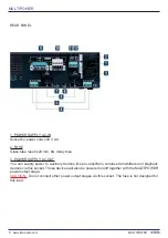
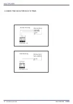
4. COMBI XLR & JACK PLUG SOCKETS
Symmetric line input socket – compatible with XLR and jack plugs.
XLR:
1…….Ground
2…….Signal
+
3…….Signal
–
Jack:
Tip……
Ring….Signal
–
5. SIGNAL INPUT TERMINALS
Alternative input to XLR / jack socket.
6. REMOTE MUTE INPUT
Remote control input for muting inputs - electrically isolated. For wiring see connectivity layout.
7. GROUNDLIFT SWITCH
If you activate “groundlift”, the device is separated from ground.
8. BRIDGE SWITCH
Switch from 2-channel to bridge mode. Bridge mode mixes inputs A and B. Input signal levels can
be set by the level controls on the front panel. For output wiring, see connectivity layout.
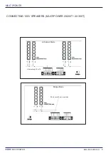
9. OUTPUT TERMINALS 100V (only for 2x200T and 2x300T)
You can connect 100V speaker systems to these terminals (see connectivity layout).
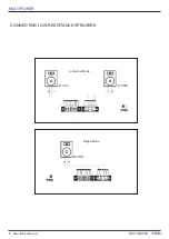
10. LOW-RESISTANCE OUTPUT TERMINALS
You can connect low-resistance speaker systems to these terminals (see connectivity layout)
11. OPERATION MONITORING
Potential-free contacts to monitor operation. Circuit closed if MULTIPOWER is ready for operation.
For wiring see connectivity layout.
12. REMOTE POWER-ON (optional)
If your MULTIPOWER is equipped with this option, you can remote control it using a 12V line (see
connectivity layout). The power switch on the front panel has to be turned on to enable remote con-
trol.
no phantom voltage
signal
1
2
3
1 earth (US = ground)
2
3 signal -
signal
earth (US = ground)
earth (US = ground)
¼” stereo jack, balanced
phantom voltage 12V
XLR plug, balanced
no phantom voltage
¼” stereo jack, unbalanced
signal


