Chapter 5 MACHINE DISASSEMBLY
UNI-5 Service Manual
5-11
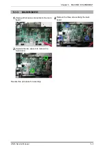
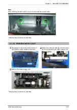
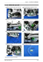
Note:
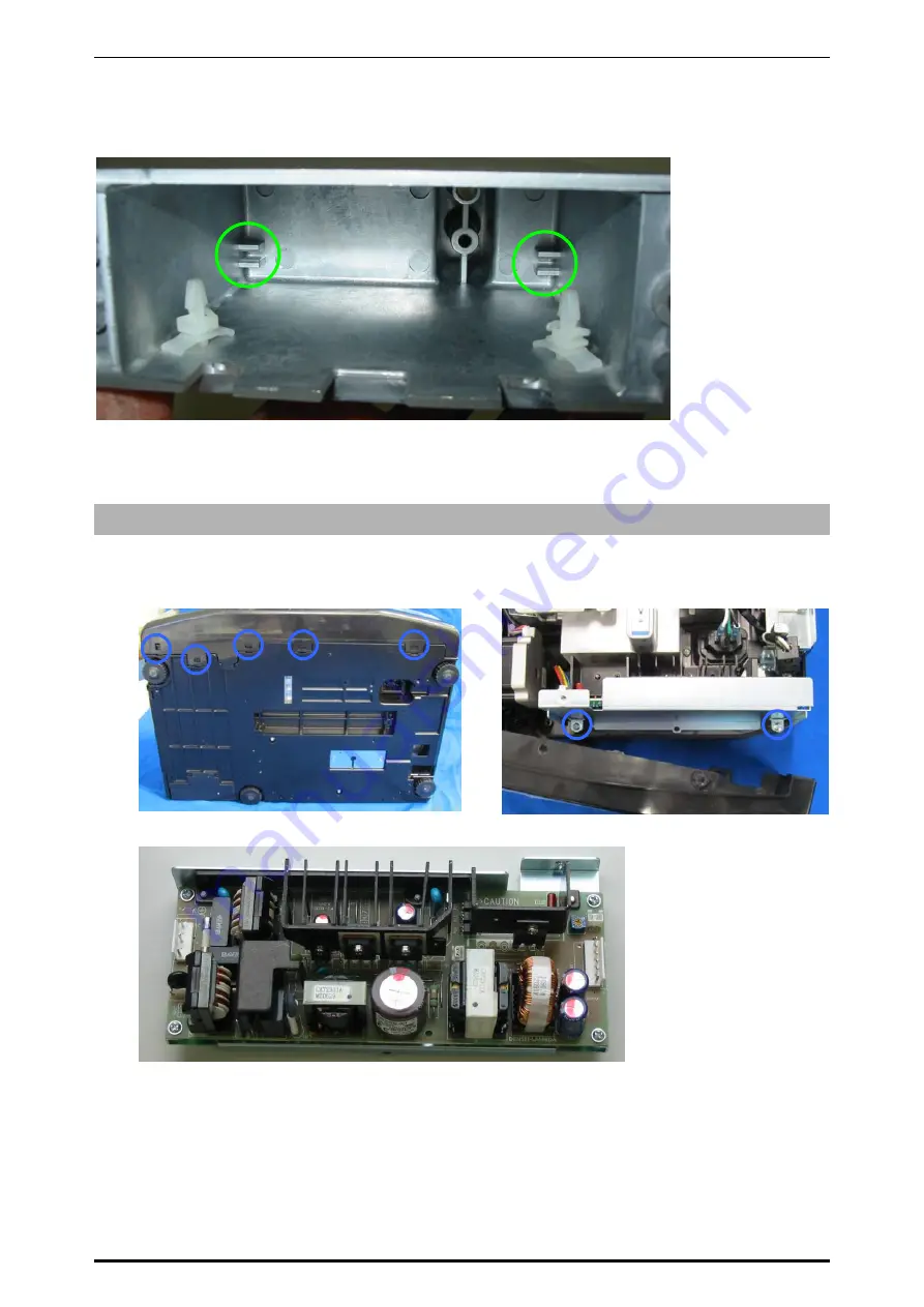
When inserting the A/D board, be sure to hold it with two hooks inside.
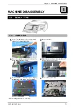
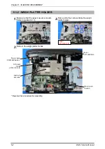
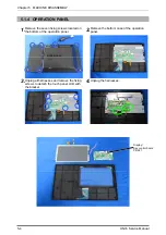
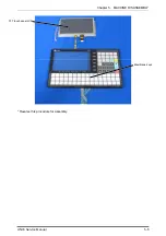
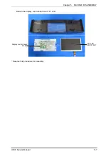
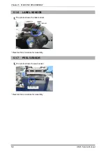
* Reverse this procedure for assembly.
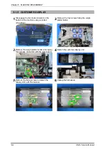
5.1.10 POWER SUPPLY UNIT
1.
Disengage the five hooks at the bottom of
the machine using a slotted screwdriver.
2.
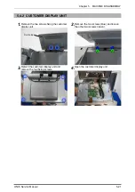
Detach the customer display unit and remove
the two screws fixing the power supply unit.
3.
Remove the power supply unit.
* Reverse this procedure for assembly.
Содержание Uni-5
Страница 11: ...Chapter 1 BASIC INFORMATION 1 2 UNI 5 Service Manual 1 1 2 OUTER DIMENSIONS FOR POLE TYPE ...
Страница 12: ...Chapter 1 BASIC INFORMATION UNI 5 Service Manual 1 3 1 1 4 OUTER DIMENSIONS FOR ELEVATED TYPE ...
Страница 16: ...Chapter 2 ASSEMBLY DRAWINGS UNI 5 Service Manual 2 1 ASSEMBLY DRAWINGS 2 1 BENCH TYPE 2 ...
Страница 18: ...Chapter 2 ASSEMBLY DRAWINGS UNI 5 Service Manual 2 3 2 2 POLE TYPE ...
Страница 22: ...Chapter 2 ASSEMBLY DRAWINGS UNI 5 Service Manual 2 7 2 5 PRINTER FOR EACH TYPE ...
Страница 24: ...Chapter 3 BLOCK DIAGRAMS UNI 5 Service Manual 3 1 BLOCK DIAGRAMS 3 1 BLOCK DIAGRAM BENCH POLE EV1 TYPE 3 ...

