IRT MFC-3465 Скачать руководство пользователя страница 6

3465&3485-mfc.ib.rev4.doc 

page 6 of 22

 17/10/2007


Technical description 

 
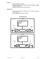
The MFC-3485 and MFC-3465 form a system for encoding and decoding the data in an ASI data stream for 
transport in a G.703 stream. The MFC-3485 takes ASI data rates from 1.5 to 30 Mb/s and adds stuffing bytes to 
convert the signal to run on a 34 Mb/s (E-3) G.703 system (MFC-3485/34, 34 Mb/s version) or ASI data rates from 
1.5 to 39 Mb/s and adds stuffing bytes to convert the signal to run on a 45 Mb/s (DS-3) G.703 system (MFC-
3485/45, 45 Mb/s version). The MFC-3465 decodes and removes the stuffing bytes to restore the original ASI data 
steam. 
 
As the MFC-3485 does the original encoding, it will be described in detail first. 
 

MFC-3485


ASI Input


The input ASI signal passes through an automatic line equalisation circuit, U1. The purpose of this equaliser is to 
restore both the signal level and the leading and trailing edges of the digital signal so that signal jitter is reduced 
prior to feeding the next stage, U2,  which is a serial to parallel data converter which feeds the main logic processor, 
U5. 
 

Logic processing, reclocking and error detection. 

The main logic processing, reclocking, error detection and operational interfacing are all performed by logic circuits 
within a custom programmed large scale logic array. The internal logic and functions of this IC are too complex to 
describe in detail and the following is intended as a guide to function only. Data rates are byte stuffed here to bring 
the rate up to standard G.703 rates depending on the version of card, i.e. 34 Mb or 45 Mb. 
 

Data loss detection. 

Receipt of an invalid ASI byte is considered a loss of data. 
 

Sync Error  

ASI packet sync has been lost at the output of the FIFO. 
 

188 TS Sync length indicator 

If the number of bytes between TS packet syncs is 188 then the 188 LED lights. When either a loss of input or sync 
loss is detected, this LED is extinguished. 
 

204 TS Sync length indicator 

If the number of bytes between TS packet syncs is 204 then the 204 LED lights. When either a loss of input or sync 
loss is detected, this LED is extinguished. 
 

Alarm relay 

An alarm output is available on the rear assembly using a two pin connector. 
The relay contact will short circuit the two pins on the rear assembly when the selected alarm condition occurs, 
selectable by link LK3 (see configuration section) or there is a loss of power to the module. 
 

G.703 Output


U4 is a G.703 data driver IC feeding a transformer to give an output on the rear connector unit. Link settings set the 
output for either HDB3 for the 34 Mb version or B3ZS for the 45 Mb (link LK1) and whether the output is shaped 
or unshaped (link LK2). See configuration section for settings. 
 

SPI Output


True SPI output is also provided on rear connector unit. 

Содержание MFC-3465

Страница 1: ...nd manufactured in Australia IRT can be found on the Internet at http www irtelectronics com I R T Electronics Pty Ltd A B N 35 000 832 575 26 Hotham Parade ARTARMON N S W 2064 AUSTRALIA National Phon...

Страница 2: ...panel connector diagrams 11 Operation 12 Front indicators 12 Maintenance storage 13 Warranty service 13 Equipment return 13 Characteristics of signal types 14 Coding characteristics 14 G 703 14 Synch...

Страница 3: ...absence of a valid MPEG ASI input the MFC 3485 will transmit all ones IRT s 34XX series of adapters provide a modular approach to connecting between the different transport types The 34XX series find...

Страница 4: ...sion of variable rates of DVB ASI to G 703 and for transport via Telecom circuits Block length indication and error detection Block diagrams MFC 3465 Alarms indications 188 BYTE BLOCK 204 BYTE BLOCK S...

Страница 5: ...ed Data rate 34 368 Mb s Output 1 x ASI C Impedance 75 Level 800 mVp p Added PCR Jitter Less than 240nS Connectors BNC Power Requirements 28 Vac CT 14 0 14 or 16 Vdc Power consumption 5 VA Other Tempe...

Страница 6: ...ale logic array The internal logic and functions of this IC are too complex to describe in detail and the following is intended as a guide to function only Data rates are byte stuffed here to bring th...

Страница 7: ...function only Data loss detection If the input level is insufficient for correct operation or if more than 180 1 s occur in a row then data loss is deemed to have occurred Sync Error After 2 consecuti...

Страница 8: ...5 feet MFC 3485 45 45 Mb s version OUT DS3 unshaped output for 225 feet MFC 3485 45 45 Mb s version Note Leave out on MFC 3485 34 34 Mb s version LK 3 LEFT Relay Alarm set to indicate on Loss of Signa...

Страница 9: ...ge of unit and local supply voltage match and that correct rating fuse is installed for local supply Earthing Particular care should be taken to ensure that the frame is connected to earth for safety...

Страница 10: ...K3 or Loss of Power MFC 3465 G 703 input This BNC input is terminated in 75 Ohms Input cable compensation is automatic for up to 450 feet of 75 Ohm coaxial cable Belden 8281 equivalent Input equalisat...

Страница 11: ...following front panel and rear assembly drawings are not to scale and are intended to show relative positions of connectors indicators and controls only INPUT SYNC 204 188 DC MFC 3465 N140 INPUT SYNC...

Страница 12: ...put as outlined below Front indicators Input loss alarm This LED lights when there is a loss of input signal or coding errors occur on the input stream Sync loss alarm This LED lights for at least 300...

Страница 13: ...be extended by IRT only to the extent obtainable from the component supplier Equipment return Before arranging service ensure that the fault is in the unit to be serviced and not in associated equipme...

Страница 14: ...transmission of variable data rates The data transfer is synchronised to the Byte clock of the MPEG transport stream The data to be transmitted are MPEG 2 transport packets The data signals are synchr...

Страница 15: ...of 1 bits and 0 bits in the transmitted serial data stream The disparity characteristics of the code maintain DC balance Special characters are defined as extra code points beyond the need to encode a...

Страница 16: ...ing of the sequence 100101010000000 into the PRBS registers is initiated at the start of every eight transport packets To provide an initialisation signal for the de scrambler the MPEG 2 sync Byte of...

Страница 17: ...branches cyclically connected to the input Byte stream by the input switch Each branch is a First In First Out FIFO shift register with depth Mj cells where M 17 N I N 204 error protected frame length...

Страница 18: ...to 8448 KHz 18 dB 8448 KHz to 12672 KHz 14 dB Electrical characteristics CCITT G 703 34368 Kb s Cable type Coaxial Impedance 75 Signal level 1 0 V Nominal pulse width 14 55 ns Code conversion HDB3 Pu...

Страница 19: ...ut regard for the underlying data rate thus simplifying system design Note that the ASI signal is polarity sensitive Although most 270 Mb s SDI DA s and switchers will pass ASI signals the line driver...

Страница 20: ...vices framing structure channel coding for 11 12 GHz satellite services ETS 300 429 Digital broadcasting systems for Television sound and data services framing structure channel coding and modulation...

Страница 21: ...PGA Field Programmable Gate Array G 703 ITU CCITT recommendation G 703 HDB3 High Density Bi polar of order 3 IF Intermediate Frequency IRD Integrated Receiver Decoder ITU International Telecommunicati...

Страница 22: ...04382 1 MFC 3465 circuit schematic G 703 to ASI converter 804382 2 MFC 3465 circuit schematic G 703 to ASI converter 804384 1 MFC 3485 circuit schematic ASI to SPI converter 804384 2 MFC 3485 circuit...

Страница 23: ...49 50 51 52 53 58 59 47 48 1 U5 BB1 RP2 U12 39 79 80 81 83 XTAL1 5 32a b TP1 78 Dvdd 4 20 33 40 45 63 5 1K 1 5 6 7 28 CKW 10 5 4 22 23 ENANot 25 5 Avdd 54 5 5 5 5 5 21a b 22a b 23a b 24a b 25a b 26a b...

Страница 24: ...WING No COPYRIGHT ARTARMON NSW AUSTRALIA 2064 A3 U5 2 28 10 98 5 18 20 11 T7295 10 38 37 U3 28ab 27ab MFC 3465 G703 TO ASI CONVERTER 14 15 16 RNDATA RPDATA RCLK 12 2 EQ 9 1 4 5 3 6 13 RIN 7 8 44 39 2...

Страница 25: ...8 7 7 7 7 6 6 6 8 8 6 5 2 3 10 11 14 13 2 3 10 11 14 13 7 1 9 15 1 9 15 61 62 73 71 72 70 69 66 67 65 64 10b 10a 9b 9a 8b 8a 7b 7a 6b 6a 5b 5a 4b 4a 3b 3a 1b 1a 11b 11a 12b 12a 31a b 1Psync 1Dvalid 1C...

Страница 26: ...38 35 2 2 28 10 98 TO SHT 1 Phase DDSclock Dclockin 4 3 2 1 8 5 6 7 Q Dvdd MAX961 5 22 23 25 4 DS3 E3 TXLEV TRING TTIP RCLK RLOOP TAOS GND GND RPDATA RNDATA 1 2 5 10 21 27 28 24 3 6 26 12 T7296 11 8...

Страница 27: ...S RCLK RLOOP TAOS GND GND RPDATA RNDATA 1 2 5 10 21 27 28 24 3 6 26 12 T7296 11 8 7 9 U4 28ab 27ab MFC 3485 ASI TO G703 CONVERTER 3 17 RCLKO3 RNEG ALARM 3 8 1 5 14a 14b 5 5 TO LED1 TO LED2 36 U5 XTAL2...

Отзывы: