background image

4

PCW Control 

S


Installation

run time duration assigned to each zone.


• 

Any number of schedules can be defined and saved 

to memory for later recall, however every schedule 

must have a unique name assignment. 

13.  Select the 

Default Schedule

 option to open the 

new schedule with a run time 

Blank Schedule

 to 

start without presets. 

14. Click the 

Finish Button.


• 

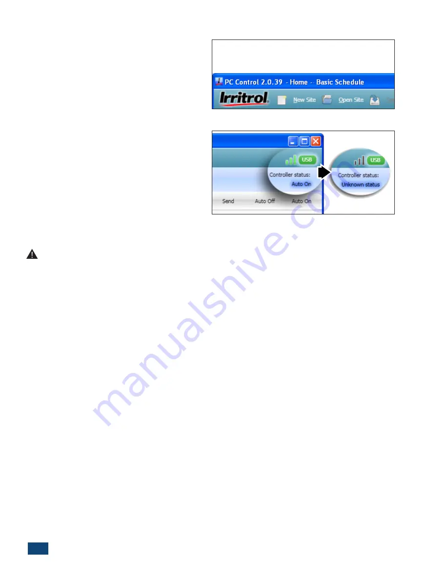
The site and schedule name will be displayed at 

the top of the program window (Figure 1.5).

The PCW Control program should begin communicat-

ing with the Controller(s) at this time and will activate 

the control system; indicated by green signal bars and 

the Auto On controller status. If a communication link 

is not established, Unknown Status will be displayed. 

(Figure 1.6) This condition is usually caused by a 

mismatching PIN. Verify the PC-R and Controller have 

a matching PIN and the Controller(s) can be operated 

manually with the PC-R.

Change PIN


Important PIN Information:

 As a security measure, the PC-Remote (PC-R) and Controller utilize a 

four-digit PIN code to enable wireless communication. Both units are initially set to 0000 by default. This 

is an optional feature and can remain 0000 if desired. If you wish to change the PIN to prevent unintended 

system operation, read this section.

Changing the system’s PIN can only be done from the computer when all the PINs are the same to begin with. 

The parts of the system, computer, PC-R, and Controller all have to be communicating for “Change PIN” to 

function. In the case of mismatched PINs (and in the case of multiple Controllers in the system), the PIN and 

controller number need to be set manually in each controller. See the procedure below:
1. On the front of the Controller, press the “MANUAL” and “AUTO ON” buttons simultaneously to start the 

“POWER” light blinking and illuminate one of the station lights.

2. With the station lights 1 thru 9 representing PIN digits 1-9 and with 10 representing “0”, use the “MANUAL” 

button to advance to and illuminate the first digit desired for the PIN.

3. Press “AUTO ON” to move the light down from “POWER” to illuminate “SIGNAL”. The “SIGNAL” light represents 

the second PIN digit. Again, use the “MANUAL” button to move to and illuminate the second, desired PIN 

number and then press “AUTO ON”.

4. Repeat the above steps to set the third and fourth PIN digits with “SENSOR” and “MASTER VALVE / PUMP” 

illuminated respectively.

5. The last digit, represented by the “TEST” light, is for the controller or Controller number. If there is only one 

controller in the system, set or leave the controller number at “1”. If setting up a second controller for the 

system, use the “MANUAL” button to move to #2 in the “STATION” lights. The controller number selection 

only goes up to four.

6. Hold down the “AUTO ON” button until the lights start a sequential display and then release the button. The 

Controller will demonstrate what was set for each of the four PIN numbers and the controller number and 

will then return to AUTO mode on its own.

Figure 1.5

Figure 1.6

Содержание PCW Control

Страница 1: ...PCW CONTROL SYSTEM User sGuide...

Страница 2: ...2 PCW Control S Installation...

Страница 3: ...ater Zone Properties 11 Selecting Lighting Zone Properties 12 Zone Control Options 13 The Scheduling AdvisorTM Panel 14 Advisor Based Schedule 15 The Site Settings Panel 16 Manual Operations Panel 19...

Страница 4: ...it personal identification number selectable for the system The PCW Control software PC Remote and the controller all must have the same PIN The user selected PIN helps reduce the chance of unau thori...

Страница 5: ...menu launch the PCW Control program 5 At the Quick Start dialog box click the New Site option button Figure 1 2 The Open Site option is used to open a previously saved site configuration file Note A S...

Страница 6: ...mputer PC R and Controller all have to be communicating for Change PIN to function In the case of mismatched PINs and in the case of multiple Controllers in the system the PIN and controller number ne...

Страница 7: ...remote USB connection and signal strength bars are located on the far right C The light blue section displays current Controller Status information including zone operation Auto On Auto Off status an...

Страница 8: ...y day beginning at 6 00 a m Calendar Control Panel The Schedule Viewer is formatted with the days of the week arranged in columns starting on Sunday and Start Times arranged in rows starting at 12 00...

Страница 9: ...rating at any given time An Overlap Limit preference on the Settings panel enables up to two additional watering zones to operate simultaneously See Site Settings Panel p 11 for complete information O...

Страница 10: ...lect an alternate Interval start day click on the blue down arrow box to display the drop down calendar The current Interval start date will be highlighted in dark blue Click on the preferred start da...

Страница 11: ...nesday and Thursday will be active This circumstance will occur at the end of all months with 31 days The Weekday Schedule The Weekday schedule enables any day of the week to be selected as active Whe...

Страница 12: ...ue arrow buttons will scroll the Zone Buttons into view Figure 2 12 Adding Zones Each site can schedule up to 12 zones If the site currently has less than 12 zones selecting the Add Zone button will o...

Страница 13: ...ller regardless of Zone Box content 3 Name Enables the zone to be labeled as preferred Note Changes in the Zone Properties menu will not be reflected in the program until the OK button has been select...

Страница 14: ...IP code must be entered in the Advisor Panel to enable the Sunset Sunrise lighting zone option See The Scheduling Advisor Panel on page 9 for details 4 Use Sunset Time to Start Select this option to a...

Страница 15: ...Zone Control Options menu when the zone is in the disabled mode Remove Zone Removes the Zone Button and all information for the zone from the Schedule Important When a zone is removed from the schedu...

Страница 16: ...ected to apply the Advisor defined zone schedule 3 Advisor ET Adjustment Use the adjustment slider to increase decrease overall watering applica tion rate of an Advisor based schedule 4 Earliest Advis...

Страница 17: ...e Advisor panel and depicted in the Schedule Viewer Figure 2 25 Note The Advisor icon will be displayed in the lower corner of a Zone Button when the Scheduling Advisor is controlling the zone waterin...

Страница 18: ...log box when opened Figure 2 27 Type in a different four digit PIN and select either of the following PIN Options as preferred Remote and Controller PINs must already match to use this option This is...

Страница 19: ...n for that controller Note The Rain Sensor option is selectable by zone within the Zone Properties menu but must first be enabled in the Site Settings panel to become available within the individual z...

Страница 20: ...n applied saved and sent to the controller Note When the All 12 Months option is selected the adjustment value will change to 10 by default for all months Be sure to set the adjust ment slider to the...

Страница 21: ...he red Edit Frame will be added to the program list by selecting the Add button The order in which Zones are added and listed determines the zone operating sequence 3 Duration Each zone is assigned a...

Страница 22: ...tton to format the manual watering program list The zone order selected will be the order of operation during the watering program Continue to add as many zones to the list as preferred Figure 2 34 Cl...

Страница 23: ...one running sta tion or zone to start another use the UP or DOWN arrow button to move from the current station and select a new station number The previous station or zone will turn off and the select...

Страница 24: ...urce 120 VAC 220 VAC etc to connect to a pump motor Like it does for a master valve the controller switches the pump on with the first station and off again once the last valve closes For irrigation s...

Страница 25: ...s the system can save water The system can be shut down for the winter months from the convenience of your computer In freezing climates this does not replace winterizing the system with compressed ai...

Страница 26: ...ion I have A The software version is shown in the top left corner of the program window You can also access the system information by selecting Tools About from the main menu Q How do I know if I have...

Страница 27: ...s when an over current condition is detected generally caused by a faulty valve solenoid or a shorted solenoid wire connection The offending zone number s will be identified on the Controller with a...

Страница 28: ...f you check the box All 12 Months the seasonal adjustment value will drop to 10 minimum value to reflect that the user wants to set all the months season adjustments If you select an individual month...

Страница 29: ...when adjusting the ET value NOT compatible with Scheduling Advisor Working with Different Adjustments The user can affect the runtimes in various ways using the different adjustment settings In the ex...

Страница 30: ...ections for Windows 7 1 Set up View options to view hidden files and folders a Double click any folder icon to open a Windows 7 window b On the now visible window click on the Organize button top left...

Страница 31: ...mb drive window 5 Put the thumb drive into the new computer 6 Navigate to the same location on this computer C Users login name AppData Roaming Irritrol If the AppData folder is not visible for this c...

Страница 32: ...te displays E1 Most likely caused by a defective IC in the remote Please contact Irritrol Support for warranty replacement Under Display Zone Start Times I highlight the start time but my edit won t c...

Страница 33: ...y such as My Documents Windows 7 C Users USER_ACCOUNT Ap pData Roaming Irritrol The software crashes or does not respond when I open a file or when using a default site Either the file you are trying...

Отзывы: