Irritrol MC-12E Скачать руководство пользователя страница 5

5

Control Wires Installation

Step 1 –  Route the valve control wires between the valves and the MC-E controller.


 For wire runs up to 1000’ between the controller and the valves, it is recommended to use an 18 AWG 

(1.0 mm

2

) multi-wire sprinkler valve connection cable. This cable is insulated for direct burial and is color 

coded to simplify installation.

Step 2 –   Attach one wire from each valve solenoid to 

the white color-coded wire from the cable. 

(Since the valve solenoid has no polarity, either 

wire can be used for this connection.) Designate 

this connection as the Valve Common.

Step 3 –  Attach a separate cable wire to each of the 

remaining valve solenoid wire. Take note of the 

wire color being used for each valve as well 

as the watering zone/area it is designated. This 

information will be important when connecting 

the valve wires to the controller’s station 

terminals.

Step 4 –  Use wire nut fasteners to secure the valve 

solenoid wire connection. Waterproof all 

connections with grease caps or similar 

insulation method.

Step 5 –  Route the other end of the control wires into the 

provided conduit hole at the bottom of the cabinet. Leave about 8” of cable remaining in the cabinet. Expose 

about 3/8” of bare wire from the station and the valve common wires.

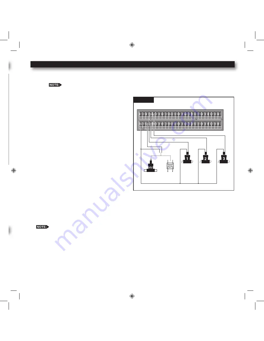
Step 6 –  Secure the valve common wire to one of the three terminals labeled “VALVE COMMON” and each valve wire 

to its appropriate station terminal designation.

*


 For flow monitoring, with a flow sensor installed, Station #1 is programmed and used as activation circuit for 

a normally-open master valve instead of a regular station valve. (See page 36 “Install Critical Flow Shut Off 

Master Valve”.)

VALVE

COMMON

VALVE

COMMON

VALVE

COMMON

MASTER

VALVE

YEL RED

VALVE

COMMON

GND

1

3

5

7

9

11 13 15 17 19 21 23 25 27 29 31 33 35 37 39 41

2

4

6

8 10 12 14 16 18 20 22 24 26 28 30 32 34 36 38 40 42

Figure 2

Cabinet Installation

Step 1 –  Selecting the proper installation site for the MC-E controller is 

essential to safe and reliable operation. The controller features 

a weather resistant cabinet designed for indoor and outdoor 

installation. The controller should be installed on a vertical wall 

or other sturdy structure near a grounded power source. Select a 

location that provides as much protection from direct sunlight, 

rain, snow and irrigation spray as possible.

Step 2 –  Drive a wood screw (provided) into the wall at eye level. 


(For Large Cabinet Unit - 18 Stations or more) Drive another 

wood screw 8” (20.3 cm) directly below the first screw. 


(For Small Cabinet Unit - 12 Stations or less) Drive another wood 

screw 5 3/4” (14.5 cm) directly below the first screw.


Leave approximately 1/4” (6.5 mm) of the screw extended from 

the wall to accommodate the cabinet.


 For drywall and masonry installation, use proper screw 

anchors to prevent the screws from loosening.

Step 3 –  Place the controller cabinet on the screws using the keyhole slots on the back panel. Ensure that the cabinet is 

installed securely on the screws. See Figure 1.

Step 4 –  Open the controller door and remove the bottom panel door. Locate the bottom screw and tighten it securely.

The MC-E series has two available lockable, weather and vandal resistant steel pedestals for free standing applications. 

For MC-E controllers with 12 stations or less, use the Irritrol P-2B pedestal. For MC-E controllers with 18 stations or 

more, use the Irritrol P-6B pedestal. Follow the installation and mounting instructions that are provided with the pedestal.

Electrical Conduit Installation

Electrical conduit and adapters are not supplied with the controller but may be required for installations in your area. 

Check with your local electrical codes and install conduit according to requirements.

For power wires, install a 1/2” (13 mm) NPT threaded conduit access body to the transformer assembly threaded nipple. 

From the access body, install conduit to the power source.

For station valve wiring, install a 2” (5 cm) conduit adapter and conduit.

Master 

Valve

Pump Start 

Relay

Station 1

*

Station 2 Station 3

*

Wiring for standard (non-flow sensing) system

Содержание MC-12E

Страница 1: ...MC E Blue Installation Instructions and Programming Guide For Controller Models MC 4E MC 6E MC 8E MC 12E MC 18E MC 24E MC 30E MC 36E MC 42E MC 48E English Espa ol Fran ais...

Страница 2: ...8 9 Current Time Pg 9 Security Password Pg 10 Set Master Valve ON or OFF per Station Pg 11 Program SETUP Assign Station Runtime to a Program Pgs 12 13 Program Start Time Pgs 14 15 Station Delay Time...

Страница 3: ...Function Dial 5 Flow Alarm Indicator LED 6 Master Valve Active Indicator LED 7 Power Supply Indicator LED Activates the LCD Display Backlight Use to navigate through the menu options Use to navigate...

Страница 4: ...ening Step 3 Place the controller cabinet on the screws using the keyhole slots on the back panel Ensure that the cabinet is installed securely on the screws See Figure 1 Step 4 Open the controller do...

Страница 5: ...nut fasteners to secure the valve solenoid wire connection Waterproof all connections with grease caps or similar insulation method Step 5 Route the other end of the control wires into the provided co...

Страница 6: ...nd into the controller terminals Step 2 Refer to the provided sensor installation guide for wiring instructions The START SENSOR will operate on any Function Dial position except for RAIN OFF CLIMATE...

Страница 7: ...tation with the problem and continue to water operable stations The sequence the controller follows is listed below 1 The controller reaches a station with a short circuit 2 The controller shuts off t...

Страница 8: ...ial to the SETUP position Step 2 The default Time and Date is set to the U S format To set the date to International format Day Month Year press To return to the default U S format press Step 3 Press...

Страница 9: ...Step 3 Enter the Hour Minutes and Seconds in H MM format Enter the H MM for PM time International setting follows the 24 hour format Example For 1 21pm enter 0121 for U S format and 1321 for Internati...

Страница 10: ...password before gaining access However manual operations are allowed Once the security password is verified the MC E will allow access to the menu functions for one hour Within that hour you will be...

Страница 11: ...e use the following procedure to select the station and Disable or Enable the master valve Step 1 Place the Function Dial to the SETUP position Step 2 Press the button The following display will be sh...

Страница 12: ...station number that exceeds the controller s station count will return an error message Press the button to clear any Key Entry Error Step 4 Enter the station runtime in MM Minutes H MM Hours Minutes...

Страница 13: ...ly entered runtime will overwrite the previous value Enter a runtime value of 0 minutes to delete Step 5 Repeat Steps 3 4 to enter modify delete additional station s from the program Step 6 Return the...

Страница 14: ...he overall runtime for that program Example Assign 5 30am to start time number 1 for program 1 by entering 0530 The 05 55am time indicated on the display is the end time This is calculated by adding t...

Страница 15: ...lear any Key Entry Error Step 3 Press the button to review all start times Each programmed start times will be displayed momentarily until the last start time is shown Step 4 Enter the start time numb...

Страница 16: ...the to activate the selection Press the button to clear any Key Entry Error Step 3 Press the and buttons to access the station delay function Step 4 Enter the station delay duration in H MM SS Hours M...

Страница 17: ...nd press Use the button for PM Example Enter 6 00am start time and 10 00pm end time Step 3 You must assign a loop delay by entering Enter the delay time in H MM or MM and press One minute loop delay i...

Страница 18: ...t Hours Minutes and press to accept Step 6 Return the Function dial to AUTO RUN position to exit SET PROGRAM Delete a Looping Start Time Step 1 Place the Function Dial to the SET PROGRAM position Step...

Страница 19: ...e selection Press the button to clear any Key Entry Error Step 3 Press the button to review the program schedule The Weekdays scheduling is the factory default If Odd or Even scheduling is activated p...

Страница 20: ...ur irrigation schedule to Odd Days of the calendar schedule you can also deactivate any day of the week Set Program Schedule to Odd Days with Excluded Days Step 1 Set watering schedule to Odd days See...

Страница 21: ...SET PROGRAM In conjunction to setting your irrigation schedule to Even Days of the calendar schedule you can also deactivate any day of the week Set Program Schedule to Even Days with Excluded Days St...

Страница 22: ...p 4 Enter the designated Skip day number and press the button 1 skip 1 day then water the next day 2 skip 2 days then water the next day etc Example Set the program to skip 4 days before activating Pr...

Страница 23: ...decrement the percentage by 10 Press to save any changes In addition you can adjust the percentage by entering the percentage number using the key pad and pressing the button to accept Example Decreas...

Страница 24: ...and the corresponding runtimes that are assigned to the selected program When pressed twice MC E will sequentially display all activated stations and their runtimes To review individual stations enter...

Страница 25: ...ar any Key Entry Error Example Erase program 8 by pressing the buttons Step 3 After the deletion the display will show the following Repeat Step 2 to delete additional programs Erasing a program will...

Страница 26: ...it or press to accept Step 3 Return the Function dial to AUTO RUN position to exit Program Erase Program Erase Complete Controller Reset Activating this function will erase all data settings in the MC...

Страница 27: ...ter the station runtime from 01 second to 30 minutes seconds must be entered with 0 first i e 45 seconds enter 045 and press the to initiate the test If no runtime is entered before pressing the butto...

Страница 28: ...he Start Sensor and Program 1 With Option 2 set to PGM 1 Start ON and the Start Sensor is activated Program 1 will turn on immediately Program 1 will repeat the cycle continuously until the start sens...

Страница 29: ...from ON or OFF during station delays Step 3 Return the Function dial to AUTO RUN position to exit Options Options 4 Option 4 is used to select the remote control device being used Activate Option 4 St...

Страница 30: ...off can also be programmed with 1 to 14 days of inactivity Activate Rain Off Step 1 Place the Function Dial to the Rain Off position Step 2 The MC E will execute a 3 second countdown to cancel any act...

Страница 31: ...unction Dial at SET PROGRAM press and If station 8 is where you want Program 2 s semiautomatic run to start press and to start the operation If you do not know which stations are in Program 2 just pre...

Страница 32: ...C E True Manual feature requires you to turn the operation off once activated Otherwise the manual operation is designed to activate until midnight Notice that the displayed manual operation runtime w...

Страница 33: ...he Remote Control position MC E will immediately stop all activities and it will start receiving commands from Sentinel Central Eicon or some of the TRC remotes As long as the function dial is in the...

Страница 34: ...tructions Pay particular attention to the flow direction and to the length of straight pipe required before and after the flow sensor Take note of the sensor size and the pulse rating for the MC E flo...

Страница 35: ...ller will energize and close the normally open master valve to shut off the irrigation main line While the controller is in AUTO RUN but idle any detected flow with no valves on will also energize sta...

Страница 36: ...he Station 1 terminal Step 3 Check for proper operation Configure Station 1 for Flow Alarm Function Step 1 Place the Function dial to the SETUP position Step 2 Press Station 1 setup screen will be dis...

Страница 37: ...ensor is measuring To learn the flow value of a specific station enter the two digit station number and press the button To learn the flow value of a group of stations enter the two digit station numb...

Страница 38: ...efore reading the flow This delay period allows the irrigation system to normalize to get an accurate flow reading The default flow delay time is set at 1 minute but can be adjusted up to 9 minutes us...

Страница 39: ...ary 24 VAC 50 60 Hz 50VA Class 2 Transformer UL and CSA Listed Export 250 VAC 50 60 Hz Secondary 24 VAC 50 60 Hz 50VA Class 2 Transformer CE and TUV Listed Output Voltage Station Output Voltage 24 VAC...

Страница 40: ...and if not installed and used in accordance with the instruction manual may cause harmful interference to the radio communications Operation in a residential area is likely to cause harmful interfere...

Отзывы: