background image

page 3

Z-

39

6

 EHT

www.ironlogic.

me

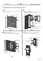
Installation onto a wooden (chipboard) locker

www.ironlogic.ru 

2

1

Make a 

2

5 mm hole in the locker's door. To mark the hole position 

use template from Fig. 13.

Connect cable to lock's PCB. 
Note: Check that cable socket is firmly connected with lock's PCB 
socket. Install the locking module according to Fig. 2.

the calculated size, depends 

on


      thickness of the locker's wall

Connect cable to 

the reader`s module

Note: Check that cable socket is firmly connected with 

readers`s 

module socket

. Install the 

reader`s

 module according to Fig. 

3

.

Locker`s door

25,0

Fig.1

A

Fig.2

 Cable

Self-tapping screw


3.5

х

15

Batteries

АА

 size 

1,5

V

Screw

 2.5х4


RESET

 button

Self-tapping screw


4

х

35

Plastic washer

Fig.3

External power 
connector

Self-tapping screw

 3х12

Reader`s module

Cover

Cable

3

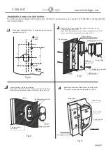
Install push bolt unit onto the locker`s wall (See Fig.4,5)
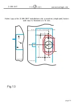
To mark the hole position use template from Fig.13

3

4

Fig.

5

Fig.

4

Self-tapping screw


3,5

х

15

Locker`s wall


Self-tapping screw


4х20

Push bolt unit

Содержание Z-396 EHT

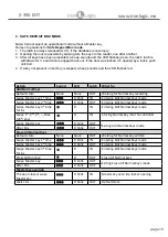
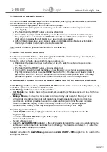
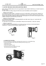
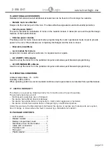
Страница 1: ...erized logging and lock setup Only works with Lock Manager software General Mode a typical lock controller operation only the key s stored in the lock s memory maximum 24 can open that lock Safe Deposit Box Mode the lock emulates safe deposit box operation To open the lock all the keys in controller database max 26 must be swipe to it one after another Custom Mode you can design your own custom op...

Страница 2: ...racelet cloning Locks setup and further use without a PC Note Logic Mode requires special Atmel T5557 keys and Lock Manager software 2 SPECIFICATIONS Working Frequency 125 kHz Keys standards EM Marine HID ProxCard II Atmel T5557 Maximum number of keys Normal 26 Master 4 NVRAM to store settings Present Reading distance 2 4cm Standby consumption current 30 µA Audio visual status indication buzzer bi...

Страница 3: ...onnect cable to the reader s module Note Check that cable socket is firmly connected with readers s module socket Install the reader s module according to Fig 3 Locker s door 25 0 Fig 1 A Fig 2 Cable Self tapping screw 3 5х15 Batteries АА size 1 5V Screw 2 5х4 RESET button Self tapping screw 4х35 Plastic washer Fig 3 External power connector Self tapping screw 3х12 Reader s module Cover Cable 3 In...

Страница 4: ...socket Install the reader s module according to Fig 8 Fig 8 External power connector Self tapping screw 3х12 Reader s module Cover Cable 3 Install push bolt unit onto the locker s wall See Fig 9 To mark the hole position use template from Fig 14 3 4 14 51 40 4 mm 4 mm 4 mm 4 mm 4 mm 2 holes 3 mm 2 holes Fig 6 Fig 7 Cable Self tapping screw 3 5х15 Batteries size АА 1 5V Screw 2 5х4 RESET button Sel...

Страница 5: ...page 5 Z 396 EHT www ironlogic me How to install the Z 396 EHT lock properly Top view View from inside the door Lock s latch push bolt unit push bolt unit Lock ...

Страница 6: ...used Allows not to tie up the key to the lock The user will decide which of the free lockers to use Works only with Lock Manager software General mode traditional lock controller operation only the keys recorded in lock s database can open the locker Safe Deposit Box mode safe deposit box mode emulation To open the lock all the keys in lock s database need to be presented to the lock one after ano...

Страница 7: ...s ready to restart the cycle from the beginning Legend beep once multiple beeps G Green LED R Red LED blink blinking page 7 Z 396 EHT www ironlogic me Action Sound LED Latch What for Default state None None OUT if a Normal key is in memory Otherwise IN Waiting for Normal key assignment Swipe a key G OUT Storing the key into the controller armed lock can be closed Swipe another key R blink IN Indic...

Страница 8: ... LED will flash the key will be erased from the lock s memory the latch will be draw inside the lock The door is now open lock is ready to restart the cycle from the beginning page 8 Z 396 EHT www ironlogic me Action Sound LED Latch What for Default state None None OUT if a locker is occupied otherwise IN Waiting for Normal key assignment Swipe a key G OUT Locker number and battery charge gets sto...

Страница 9: ...Master key 1st time R blink IN Entering Edit Normal Keys mode Swipe Master key 2nd time R blink OUT Entering Edit Normal Keys mode Swipe Master key 3rd time for 6 s R IN Entering Edit Normal Keys mode Swipe 1st 2nd 3rd Max 26th keys G IN Recording Normal Key into the controller Swipe Master key R blink OUT Exiting Add Normal Keys mode After 5 s R blink OUT Erase All Normal Keys Default state None ...

Страница 10: ...pe Master key 1st time R blink IN Entering Edit Normal Keys mode Swipe Master key 2nd time R blink OUT Entering Edit Normal Keys mode Swipe Master key 3rd time for 6 s R IN Entering Edit Normal Keys mode Swipe 1st 2nd 3rd Max 24th keys G IN Storing Normal Key into the controller Swipe Master key R blink OUT Exiting Add Normal Keys mode After 10 s R blink OUT Erase All Normal Keys Default state Non...

Страница 11: ...sual signal will appear at 6 s and 16 s from the moment the RESET button was pressed down The beep and visual signal at 16 s will confirm that the device is now reset to factory defaults 12 PROGRAMMING USING Z 2 USB RF 1996 ADAPTER AND LOCK S MANAGER SOFTWARE Lock s Manager software along with Z 2 USB RF 1996 adapter takes care about configuration set up and further operations of electronic furnit...

Страница 12: ...fully discharged If on Normal key swipe the LED is not flashing AND the lock s latch doesn t pop out it means that lock s batteries are fully discharged In Logic mode the lock records the current battery charge level into the token on each lock opening Batteries replacement The lock s electronics include NVRAM for lock settings and keys so they are not lost after batteries replacement To replace t...

Страница 13: ...ming LOCK S MANAGER software Used to set up the locks from the portable computer and subsequent bracelets programming 16 OPERATING CONDITIONS Ambient temperature 5 40 C Humidity 98 at 25 C When operating under non recommended conditions device parameters can deviate from specified values 17 LIMITED WARRANTY This Device is covered by limited warranty for 24 months since the purchase date The warran...

Страница 14: ...iga Latvia E mail info ironlogic lv headstaff ironlogic lv Phone 37166181894 37124422922 www ironlogic me The symbol of crossed throught waste bin on wheels means that the product must be disposed of at f separate collection point This also applies to the product and all accessories marked with this symbol Products labeled as such must not be disposed of with normal household waste but should be t...

Страница 15: ...ith door s thickness in 16 mm Holes Layout for Z 396 EHT installation onto a wooden chipboard locker with door s thickness in 16 mm Fig 13 Z 396 EHT www ironlogic me page 15 51 28 82 Locker s wall 28 68 mm size depends on locker chipboard wall thickness 25 mm Locker s door ...

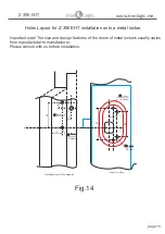
Страница 16: ... 40 40 4 mm 4 mm 4 mm 4 mm 4 mm 6 mm 2 holes 3 mm 8 9 51 Sectional view of the sidewall Locker s door 2 holes 4 mm 4 mm 4 mm 4 mm 4 mm 2 holes Important note The size and design features of the doors of metal lockers usually varies from manufactuter to manufacturer Please consult with us before installation ...

Отзывы: