


IPU 40108
Page 7 of 29
3.4
Using the IRI 4010 Thermal Imager
3.4.1
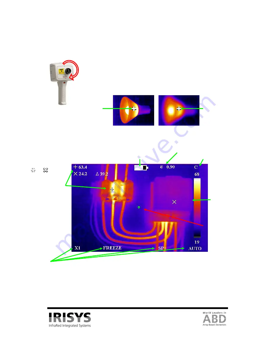
Focusing
Figure 8: Focusing
.
3.4.2
Screen Display Items
Figure 9: Screen Display Items
CAUTION: The calibrated temperature output is the figure adjacent to the cursor identifier; the temperature
scale and display colours are indicators only.
Scene emissivity
The centre green
circle to which the
laser pointer is
aligned at a
distance of 3m.
The
and
shaped
temperature
measurement cursors
(called SP+ and SPX)
and their temperature
measurement values, and
their temperature
difference value (
∆
).
Battery life indicator.
Temperature
units (˚C).
Temperature scale
with the maximum
and minimum
values of the span.
Four hot button labels.
If the imager is not focused, the image quality will be poor and temperature
measurements will not be accurate.
Rotating the lens in a clockwise direction (from front view) focuses the imager at
longer distances up to infinity. Rotating the lens in the opposite direction focuses
the imager at shorter distances down to a minimum of 30 cm.
Rotate the lens until the image has the best definition, and has the sharpest contrast
at object edges.
Focused
54°C measured.
Not focused
46°C measured.


