


8
9 Connect Camera
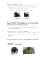
1. For the Alliance-mx IQM30 & IQM31 series cameras,
route and connect the Power-over-Ethernet cable to
the Ethernet connector port in the camera as shown
in Figure 9.1.
For the Alliance-mx IQM32 series cameras attach
the supplied ferrite clamp to the Ethernet cable, and
connect the cable to the Ethernet connector port in
the camera as shown in Figure 9.2.
2. Route and connect the optional (not supplied) audio
cable when using an external microphone and
powered loudspeaker (not supplied) to the Alliance-mx
dome camera as shown in Figure 9.3.
The external microphone and powered loud-
speaker (not supplied) will connect to 3.5 mm
audio connectors.
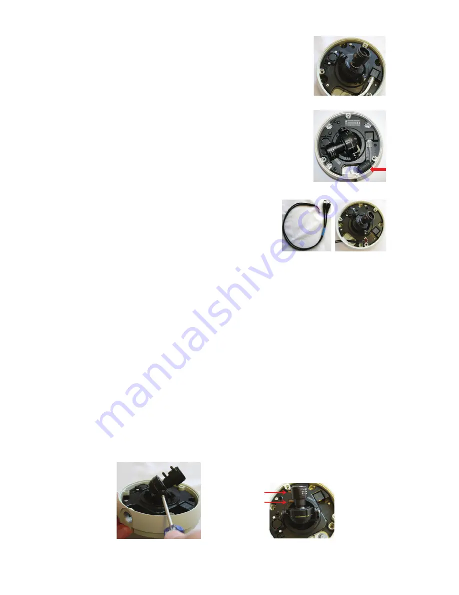
10 Camera Positioning, Field-of-View Set-up and Focus
1. Set the field-of-view using the 3-axis gimbal. Determine camera pan direction
by gripping the camera assembly, and carefully pivot the camera to the viewing
direction.
2. Adjust the tilt of the camera by loosening the tilt angle lock screws as shown in
Figure 10.1, and tilt the camera to the viewing direction. When finished, tighten
the tilt locking screws.
3. Adjust the field-of-view and focus rings to achieve the desired focus as shown
in Figure 10.2.
NOTE: The lens on the Alliance-mx dome camera is fixed iris and therefore no iris adjustment
is needed.
When finished, tighten the thumbscrews on the lens.
Figure 9.1
Figure 10.1
Figure 10.2
Figure 9.2
Optional Audio
In/Out Cable
Assembly
Audio cable can
Only Pass Through
the Conduit Entry
Focus Control
Zoom Control
Figure 9.3


