6
7 Removal of Dome Cover
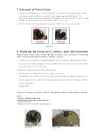
1. Using the supplied Torx T-20 security wrench, loosen the three tamper-proof
screws holding the dome cover to the enclosure assembly (Figure 7.1).
Note that these screws are captive, and held to the dome cover. These screws
should not be removed from the dome cover trim ring.
2. Lift the dome trim ring with shroud away from the camera assembly.
8 Mounting the Enclosure, Camera, and Lens Assembly
Mounting to masonry or other durable surface wall, ceiling or overhang
with cables routing through the wall or ceiling.
1. Position the supplied mounting template on the surface in the location where
the camera will be installed. Trace and drill the mounting holes and the cable
pass through hole as indicated.
2. Route the network cable through the wall.
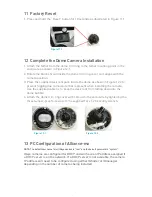
3. Gently push the Ethernet cable through the gasket
installed in the enclosure. Pull enough cable through the gasket to attach an
RJ-45 network connector, and to allow the network connector to plug into the
Ethernet socket
(Figure 8.1).
It may be necessary to pierce a hole in the gasket with an Awl tool (not supplied).
NOTE:
• Do not cut the gasket with a knife.
• Do not force the Ethernet cable with connector
through the gasket.
• Only pass one cable through the supplied gasket.
Figure 8.1
Figure7.1
Figure 8.2


