11
i Po r t I W- 2 0 / I W- 2 1 / I W- 2 2
I n s t r u c t i o n M a n u a l
iPort IW-22: Installing the Balanced Audio and RS-232 Circuit Cards
The iPort IW-22 is shipped from the factory with the appropriate balanced audio and RS-232 control circuit cards included in
the box, but
THEY ARE NOT INSTALLED IN THE IPORT’S BACKPLANE PCB. For these functions to work, you must install
these cards into the iPort’s backplane circuit board
BEFORE installing the iPort into a wall.
Before beginning, locate the two circuit cards in the iPort box.
• The Balanced Audio circuit card is
WHITE.
• The RS-232 control circuit card is
BLUE.
Use care when handling the circuit cards:
• Avoid squeezing or bending any of the electronic components mounted on the cards.
• Do not force the cards into their connectors. They will only fit into the connectors one way.
• Be sure to insert the cards all the way into their connectors.
Installing the Balanced Audio Circuit Card
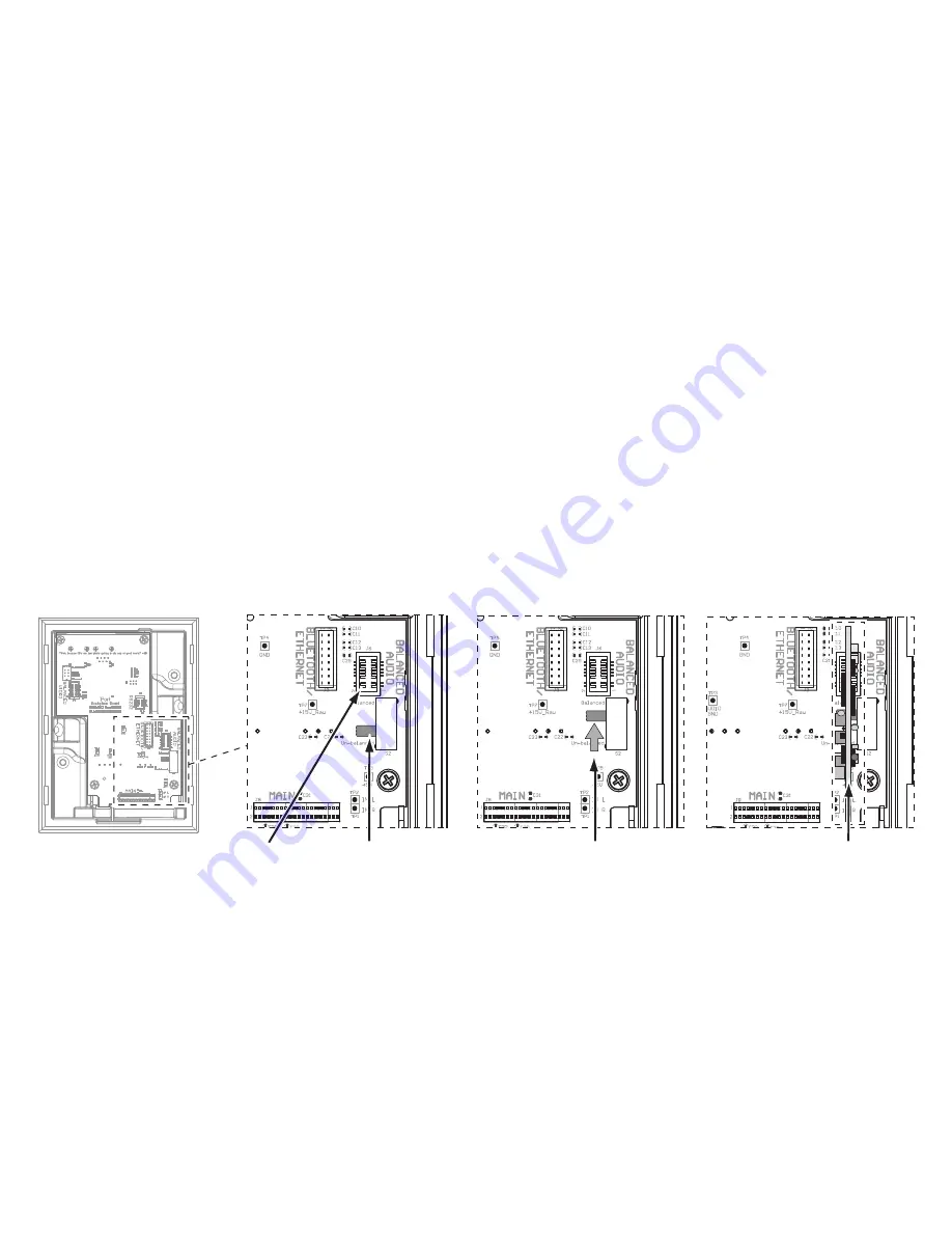
1. Locate the balanced audio PCB Connector and B
ALANCED
/U
NBALANCED
audio switch on the iPort backplane circuit board
(see
Figure 8a). The backplane circuit board is red, and it is located at the rear of the iPort chassis utility box.
2. Slide the B
ALANCED
/U
NBALANCED
audio switch UP to the
Balanced position (see Figure 8b).
NOTE: The balanced audio circuit card cannot be installed unless the switch is in the
Balanced
position.
3. Carefully insert the balanced audio circuit card all the way into the balanced audio PCB connector (see
Figure 8c).
Note: The circuit card will only fit into the connector one way. Although the circuit card fits somewhat
loosely, when the iPort face is inserted into the utility box it holds the card in place.
Slide Switch
UP
Balanced Audio
PCB Connector
Balanced/Unbalanced
Audio Switch
Insert Balanced
Audio PCB Card
A B
C
Figure 8: Installing the Balanced Audio Circuit Card
Содержание IW-20
Страница 1: ...Instruction Manual IW 20 IW 21 IW 22 ...
Страница 19: ...19 iPor t IW 20 IW 21 IW 22 Instruction Manual Notes ...


