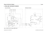


Piping and Instruments Diagram
Page 27
Operating manual LC 340.01-A.3.5/6
Current revision status: Apr 4, 2019
Component name
Electric designation Measurement / Operation
Water pump optic circuit
M5
Tank heater optic circuit
E2
Magnetic valve
Y1 (SOL 1)
Cooling of the optic circuit
Magnetic valve
Y2 (SOL 2)
Conductivity of DI-Water
Liquid level switch
B3
Refilling required
Liquid level switch
B4
Dry run protection pump
Pressure sensor
B7
Pressure optic circuit
Temperature sensor
B12
Temperature optic circuit
Conductivity sensor
A3 (A4)
Conductance optic circuit
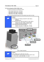
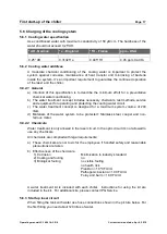
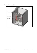
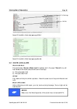
Figure 8: Hydraulic module
Pump M4.1
Solenoid Y1 (SOL 1)
Sensor B5
Sensor B1
Sensor B2
Heater E1
Heater E2
Sensor A3 (A4)
Sensor B4
Sensor B3
Sensor B12
Sensor B7
Sensor B11
Pump M5
Pump M4.2
Solenoid Y2 (SOL 2)


