Model : SK-Hybrid BP Series User’s Manual
PAGE 11 OF 16
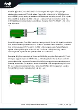
For SAS application, The LEDs behave by following SGPIO signal coming through
sideband bus inside the SFF-8643 cables. Please refer to Section 2 for SGPIO settings.
When SGPIO Jumper setting is enabled the LEDs behave according to the SGPIO signals.
When SGPIO is disabled, the RED LEDs (for Locate and Fail) do not behave while the
GREEN LEDs (for Activity) behave according to the signal from P11 (READY LED) of the
disk connectors.
For NVMe application, The LEDs behave according to the VPP over I2C signals from NVMe
host controllers through sideband bus of Oculink or SlimSAS cables. Whenever the NVMe
host controller support VPP over I2C, the RED LEDs behave Locate, Fail and Rebuild
signals following VPP signals on the I2C bus. The Green LEDs (for Activity) behave
according to the signal from P11 (Activity) of the disk connectors.
Examples of NVMe connections to Broadcom RAID/HBA controller. Each pair of VPP over
I2C signal supports 2 pieces of NVMe disks LED management. The I2C bus is leaded to
odd-number NVMe connector (Oculink or SlimSAS) to manage its corresponding and the
following NVMe disks. For example, NVMe1 and NVMe2 LED management signal is form
NVMe1 connector’s sideband I2C bus, NVMe3 and NVMe4 LED management signal is
from NVMe3 connector’s sideband I2C bus and …etc.


