Model : SK-Hybrid BP Series User’s Manual
PAGE 7 OF 16
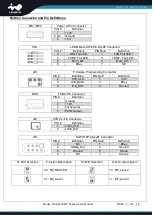
Bottom Connector and Pin Definitions
PW1/PW2
Power 4-Pin Connector
PIN #
Definition
1
+12V
2 & 3 Ground
4
+5V
CN1
LED & Mute SW 8Pin-Key#8 Connector
PIN #
Definition
PIN No#
Definition
2
FAN Fail LED -
1
FAN Fail LED +
4
TEMP_Fail LED -
3
TEMP_Fail LED +
6
Mute_SW -
5
M
8
#Key
7
NC
JD1
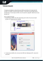
Firmware Programming Connector
PIN #
Definition
PIN No#
Definition
2
ICE_CLK
1
VCC
4
ICE_DATA
3
#Key
6
ICE_RST
5
Ground
FAN1
FAN 4-Pin Connector
PIN #
Definition
1
Ground
2
+12V
4
Tachometer
5
PWM Output
JB1
SYNC 2-Pin Connector
PIN #
Definition
1
LINK_CLK
2
LINK_DAT
JS1
SGPIO 8Pin-Key#1 Connector
PIN #
Definition
PIN No#
Definition
2
NC
1
#Key
4
SData_Out
3
Ground
6
Ground
5
SLoad
8
NC
7
SClock
S1 M/S Selection
Function Description
S1 M/S Selection
Function Description
00 : BP_MASTER
10 : BP_slave2
01 : BP_slave1
11 : BP_slave3


