SECTION 2—INSTALLATION
11
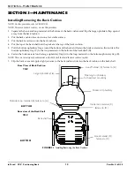
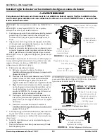
Installing/Removing Lateral Supports and/or Pelvic Stabilizers
NOTE:
For
this
procedure,
refer
to
NOTE:
To
remove
the
lateral
supports
or
pelvic
stabilizers,
reverse
this
procedure.
NOTE:
If
the
InTouch
PCS
Positioning
Back
is
used
on
a
power
wheelchair
that
has
a
MK6i™
connector
tray
attached
to
the
back
shell,
it
may
be
necessary
to
remove
the
two
screws
and
hex
nuts
that
attach
connector
tray
to
the
back
shell
to
gain
access
to
the
slots.
Before
removing
the
screws,
make
note
of
the
orientation
of
the
connector
tray
while
it
is
still
attached
to
the
back
shell.
NOTE:
The
lateral
supports
and
pelvic
stabilizers
can
be
installed
at
any
position
on
the
back
shell
that
is
best
for
the
user
and
MUST
ALWAYS
be
attached
with
two
socket
screws
and
flat
washers.
NOTE:
A
7/16
wrench
is
required
for
this
procedure.
NOTE:
The
Lateral
Support
can
be
adjusted
up
or
down
in
the
upper
slots
in
1”
increments.
NOTE:
The
Pelvic
Stabilizer
can
be
adjusted
up
or
down
in
the
lower
slots
in
1”
increments.
1.
Determine
the
desired
position
to
attach
the
lateral
or
pelvic
stabilizers
on
the
back
shell.
2.
Remove
the
two
screws
and
hex
nuts
that
attach
the
connector
tray
mounting
brackets
to
the
back
shell.
If
the
wiring
is
already
in
place,
let
the
MK6i
connector
tray
and
brackets
hang
loosely
from
the
wiring.
3.
For
each
pelvic
stabilizer
or
lateral
support,
attach
to
the
back
shell
with
two
socket
head
screws
and
washers.
4.
Attach
the
connector
tray
mounting
brackets
to
the
back
shell
with
two
screws
and
hex
nuts.
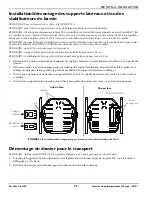
FIGURE 2.10
Removing the Back for Transport
NOTE:
Both
latches
MUST
be
in
the
up
(unlocked)
position
to
remove
the
back.
1.
On
each
back
mounting
bracket,
slightly
pull
out
as
you
rotate
the
bottom
of
the
latch
180°
to
the
up
(unlocked)
position.
2.
Lift
the
back
off
of
the
back
cane
mounting
assemblies.
Pelvic
Stabilizer
Lateral Support
Front view
Hex Nuts
Screws
MK6i connector tray
Back view
Slots


