background image

SECTION 2—INSTALLATION

Part No 1163138

7

InTouch

 PCS

™ 

Positioning Back

Installing the Back

NOTE:


This


procedure


does


not


apply


to


Invacare


Power


Wheelchairs


with


Power


Recline.


Refer


to


Installing


the


Back

 ‐ 

Invacare


Power


Wheelchairs


with


Power


Recline


on


page 10

.

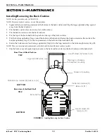
Install the Back Cane Mounting Assemblies

NOTE:


For


this


procedure,


refer


to


FIGURES


2.1


through


2.3.

NOTE:


To


remove


the


back


cane


assemblies,


reverse


this


procedure.
NOTE:


It


may


be


necessary


to


raise


or


lower


the


back


canes


to


achieve


the


desired


height


installation.


Refer


to


Owner’s


Manual


shipped


with


wheelchair.

NOTE:


DO


NOT


disassemble


the


back


cane


mounting


assemblies


during


STEP


1


of


this


procedure.

1.

Loosen,


but


DO


NOT


remove,


the


socket


head


screws


on


the


back


cane


mounting


assemblies,


just


enough


to


allow


the


back


cane


mounting


assemblies


to


slip


onto


the


back


canes.


NOTE:


Some


wheelchairs


have


back


canes


with


a


bend.


Make


sure


that


the


back


cane


mounting


assemblies


are


completely


above


or


below


and


not


straddling


the


bend.

NOTE:


There


is


a


left

hand


and


a


right

hand


back


cane


mounting


assembly


used


with


each


InTouch


PCS


Positioning


Back.


When


installed


properly,


the


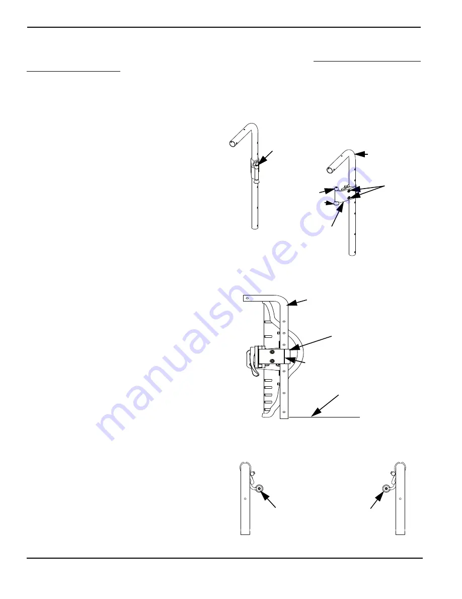
ball


is


up


and


the


cone


is


down,


as


shown


in


FIGURE


2.1.

2.

Slide


the


back


cane


mounting


assembly


onto


the


back


cane.

3.

Align


the


scored


vertical


line


on


the


outside


back


cane


mounting


assembly


with


the


center


of


the


back


cane


as


shown


in


FIGURE 2.2.

4.

Adjust


the


back


cane


mounting


assemblies


until


the


ball


and


cone


on


each


assembly


is


positioned


inward


of


the


back


canes


as


shown


in


FIGURE


2.3.

5.

Loosely


tighten


the


socket


head


screws


on


the


back


cane


mounting


assembly.

NOTE:


DO


NOT


tighten


the


socket


head


screws


completely


until


the


back


is


installed


and


centered


between


the


back


canes.

6.

Repeat


STEPS


1

 ‐ 

5


to


install


the


opposite


back


cane


mounting


assembly


onto


the


opposite


back


cane.

FIGURE 2.1   

Check hardware orientation

FIGURE 2.2   

Check vertical alignment

FIGURE 2.3   

Check ball and cone position

Right-Hand Back Cane

Mounting Assembly

Back Cane

Ball (up)

Cone (down)

Socket Head 

Screws

NOTE:


This


view


is


from


the


back


of


the


wheelchair,


looking


at


the


back


canes.

Left-Hand Back Cane

Mounting Assembly

Scored Vertical Line

(align with center of back cane)

Right-Hand Back Cane 

Mounting Assembly

Seat

NOTE:


This


view


is


looking


at


the


right


side


of


the


wheelchair.

Back Cane

Ball and cone on back cane mounting 

assemblies MUST be installed inward 

of the back canes

NOTE:


This


view


is


from


the


top


of


the


wheelchair,


looking


down


at


the


seat.

Inward of Back Canes

Содержание InTouch PCS ITPCSR

Страница 1: ...EALER This manual MUST be given to the user of this product USER BEFORE using this product read this manual and save for future reference InTouch PCS Positioning Back Models ITPCSR ITPCST ITPCSR16 ITP...

Страница 2: ...TIONS CONTACT A QUALIFIED DEALER OR INVACARE TECHNICAL SUPPORT BEFORE ATTEMPTING TO USE THIS EQUIPMENT OTHERWISE INJURY OR DAMAGE MAY RESULT ACCESSORIES WARNING Invacare products are specifically desi...

Страница 3: ...Mounting Assemblies 7 Install Adjust the Back on the Back Cane Mounting Assemblies 8 Adjusting the Back Depth and or Angle 9 Installing the Back Invacare Power Wheelchairs with Power Recline 10 Instal...

Страница 4: ...S DOCUMENT IS SUBJECT TO CHANGE WITHOUT NOTICE MAINTENANCE Maintenance MUST be performed ONLY by qualified personnel SIGNAL WORD MEANING DANGER Danger indicates an imminently hazardous situation which...

Страница 5: ...f skin or individual limitations and needs All seating systems should be selected carefully Working with your therapist physician and equipment supplier is the best way to assure that a seating system...

Страница 6: ...the chair before installation Refer to Owner s Manual shipped with wheelchair 2 Install the back Refer to the table below for applicable installation and adjustment instructions TYPE OF INSTALLATION...

Страница 7: ...and the cone is down as shown in FIGURE 2 1 2 Slide the back cane mounting assembly onto the back cane 3 Align the scored vertical line on the outside back cane mounting assembly with the center of t...

Страница 8: ...etheadscrewsthatsecure the washer plate nut plate and back mounting bracket to the back shell C Adjust the hardware until the desired height is obtained and the receivers are fully seated onto the bac...

Страница 9: ...s to the back cane mounting assemblies 2 Adjust the back to the desired depth and or angle 3 Tighten the socket head screws securing the washer plates and back shell mounting brackets to the back cane...

Страница 10: ...the desired position on the back canes 7 Loosely tighten the hex head screws NOTE If no other height adjustment is necessary proceed to STEP 11 of this procedure 8 On each side of the wheelchair loos...

Страница 11: ...Lateral Support can be adjusted up or down in the upper slots in 1 increments NOTE The Pelvic Stabilizer can be adjusted up or down in the lower slots in 1 increments 1 Determine the desired position...

Страница 12: ...e back and fasten the hook material on the inside of the bottom upholstery flap C to the loop material on the bottom of the back shell D 6 Fasten the hook material on the large upholstery flap A to th...

Страница 13: ...s and or plastics are found to be deformed breaking worn and or compressed Corrective maintenance can be performed at or arranged through your equipment supplier The back cushion cover is designed to...

Страница 14: ...cate nature of the defect and if the product is serialized indicate the serial number Do not return products to our factory without our prior consent LIMITATIONS AND EXCLUSIONS THE FOREGOING WARRANTY...

Страница 15: ...T tre remis l utilisateur de ce produit UTILISATEUR AVANT d utiliser ce produit veuillez lire ce manuel et le conserver pour consultation ult rieure Dossier de positionnement InTouch PCS Mod les ITPCS...

Страница 16: ...IBUTEUR QUALIFI OU LE PERSONNEL TECHNIQUE D INVACARE AVANT D UTILISER CET QUIPEMENT SOUS PEINE DE RISQUER DE CAUSER DES BLESSURES OU DOMMAGES AVERTISSEMENT CONCERNANT LES ACCESSOIRES Les produits Inva...

Страница 17: ...ants des tiges en canne du dossier 21 Installer r gler le dossier sur les montants des tiges en canne du dossier 22 R glage de la profondeur et ou de l angle du dossier 23 Installing the Back Invacare...

Страница 18: ...ODIFICATION SANS AVIS PR ALABLE ENTRETIEN L entretien DOIT tre efectu EXLUSIVEMENT par du personnel qualifi MOT INDICATEUR D FINITION DANGER Danger indique une situation hasardeuse imminente laquelle...

Страница 19: ...ge doit tre soigneusement s lectionn Il est recommand de collaborer avec votre th rapeute m decin ou fournisseur d quipement pour garantir le choix du syst me de si ge le mieux adapt vos besoins Si l...

Страница 20: ...ation exp di avec le fauteuil roulant 2 Installer le dossier Se r f rer au tableau ci dessous pour une les instructions d installation et de r glage TYPE D INSTALLATION POUR LES INSTRUCTIONS D INSTALL...

Страница 21: ...e haut et le c ne vers le bas comme le montre le FIGURE 2 1 2 Glisserlemontantdelatigeencannesurlatigeencanne du dossier 3 Aligner la rainure verticale sur le montant de la tige en canne du dossier ex...

Страница 22: ...e boulonnage la plaque crous et le support de fixation du dossier la coquille du dossier C R gler les ferrures la hauteur souhait e et jusqu ce que les logements soient compl tement fix s sur les mont...

Страница 23: ...x montants des tiges en canne du dossier 2 R gler le dossier la profondeur et ou l angle souhait es 3 Serrer les vis t te creuse qui retiennent les plaques de boulonnerie et le support de fixation de...

Страница 24: ...ait e sur les tiges en cannes 7 Serrer l g rement les vis t te hexagonale REMARQUE apr s avoir effectu les r glages de hauteur n cessaires passer l TAPE 11 de cette proc dure 8 De chaque c t du fauteu...

Страница 25: ...fentes du haut tous les 2 5 cm REMARQUE le stabilisateur de bassin peut tre lev ou abaiss dans les fentes du haut tous les 2 5 cm 1 D terminer la position souhait e pour attacher les supports lat rau...

Страница 26: ...Tirer le rabat en tissu du bas sous le bas du dossier et attacher le crochet l int rieur du bas du rabat en tissu C la bride du bas de la coquille D 6 Attacher la bride du gros rabat en tissu A la br...

Страница 27: ...us s et ou cras s Un entretien correctif peut tre effectu ou arrang par votre distributeur de mat riel La housse du coussinet est con ue pour prot ger la mousse de l humidit et est compos e d un mat r...

Страница 28: ...ant au dos Fournir le nom du distributeur son adresse le num ro du mod le la date d achat indiquer la nature du d faut et le num ro du produit s il est num rot en s rie Ne pas retourner de produit not...

Отзывы: