background image

Jump Starter Pack Device Operation Instructions 


ACR/QA 1829Nov


Section-B) Jump Starter Pack Device Use Continued:


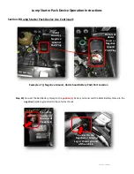
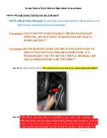
Example of (-) Negative Ground, Under-hood Battery Post/Port Location


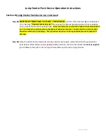
Step #4) Connect the Red Battery Clamp to the 

positive (+) 

battery terminal and the Black Battery Clamp to the 


 negative (-) cable grounded to the vehicles chassis. 


Connect to the 

 Negative (-) Ground 

Lug or chassis ground 

of the vehicle 

Connect to 

 Positive (+) 

Terminal of 

the vehicle 

DETAIL of 

Under 

Hood (-) 

Negative 

Ground   

Post/Plug 

Under 

Hood (-) 

Negative 

Ground   

Post/Plug 

Содержание PWR 7010

Страница 1: ...gine Starter Amp Rating Capacity c Vehicle Engine Liter Size 2 Jump Starter Pack Operation Use Instructions For the long term life and durability of your jump starter pack device it should be fully charged prior to use Supplemental maintenance charging should be provided to keep the jump starter pack device in full functioning order when unexpected supplemental vehicle battery boosting is needed A...

Страница 2: ...the proper jump starting of the vehicle make certain that the jump starter device is fully charged before using Step 1 Before using your the jump starter pack device TO ACTIVATE PRESS RELEASE THE POWER BUTTON THAT IS LOCATED ON THE SIDE OF THE JUMP STARTER PACK DEVICE Once activated Confirm the indicator levels before using Determine the power indicator level by either the Number of Bars or Dots i...

Страница 3: ...es battery is located in the engine compartment For some vehicle manufacture s with jump starter battery post port under hood have batteries that are located in the boot trunk under the seat or in the front fender wheel well areas of the vehicle Verify with the manufactures specifications for the vehicles location for proper jump starting EC5 Connector Insert EC5 Connector Into Port Plug EC5 Port ...

Страница 4: ... Port Location Step 4 Connect the Red Battery Clamp to the positive battery terminal and the Black Battery Clamp to the negative cable grounded to the vehicles chassis Connect to the Negative Ground Lug or chassis ground of the vehicle Connect to Positive Terminal of the vehicle DETAIL of Under Hood Negative Ground Post Plug Under Hood Negative Ground Post Plug ...

Страница 5: ...ing locate the Manual Activation Button that is located on the side of the Smart Clamp Safety Box Then press and hold the Manual Activation Button for 1 to 3 seconds and then release the Manual Activation Button Additionally the Indicator light should be illuminated and not flashing If all previous steps are correctly connected your device set up should look similar to this View of typical under h...

Страница 6: ...NG MAKE CERTAIN TO CHECK FOR LOOSE OR POOR FITTING POST AND TERMINAL CONNECTIONS IT IS RECOMMENDED THAT THE BATTERY POSTS TERMINALS ARE CLEAN CORROSION FREE AND TIGHTENED Step 6 Attempt to start the vehicle If the vehicle starts runs under its own power proceed to Step 9 Step 7 If the vehicle does not start or run under its own power and requiring an additional jump start attempt the following act...

Страница 7: ... Once located press and hold the Manual Activation Button for 1 to 3 seconds and then release the Manual Activation Button Confirm that the indicator light should be solid and not flashing This procedure may have to be repeated before each jump start attempt Step 9 Once the vehicle has started and is running under its own power safely disconnect the jump starter pack devices Smart Clamps red posit...

Отзывы: