4
July 15, 2010
AN1568.0
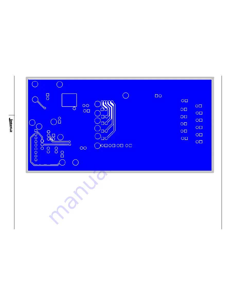
FIGURE 4. EVALUATION BOARD BOTTOM LAYER
Application Note 1568
Страница 1: ...abled in this mode 10 Inserting JP7 allows the dimming frequency to be programmed with a resistor R12 to GND The dimming frequency is calculated by Equation 1 11 Switches SW1 and SW2 are used to program the switching frequency and enable the equal phase shift feature per Table 1 For additional information please consult the ISL97676 data sheet 12 After following Steps 1 through 9 all 72 LEDs shoul...
Страница 2: ...LED36 LED37 LED38 LED39 LED52 JP13 LED51 LED50 LED49 LED48 LED47 LED46 LED45 LED44 JP14 LED55 LED56 LED57 LED58 LED59 LED60 LED61 LED62 LED64 LED65 LED78 LED77 LED76 LED75 LED74 LED73 LED43 LED42 LED41 LED40 LED53 LED63 LED72 LED54 LED71 LED70 LED69 LED68 LED67 LED66 JP16 JP17 JP18 JP19 JP20 JP15 C15 4 7nF C14 4 7nF C13 4 7nF C12 4 7nF C16 4 7nF C17 4 7nF J14 Vout JP8 JP24 JP23 JP22 JP21 JP25 JP26...
Страница 3: ...3 July 15 2010 AN1568 0 FIGURE 3 EVALUATION BOARD TOP LAYER Application Note 1568 ...
Страница 4: ...4 July 15 2010 AN1568 0 FIGURE 4 EVALUATION BOARD BOTTOM LAYER Application Note 1568 ...