


Application Note 1657
4
AN1657.0
August 12, 2011
Using the ISL76683 Light Sensor
Evaluation Software
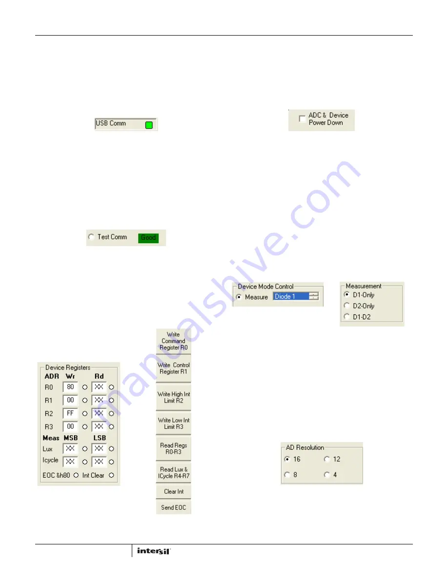
USB Communications
In the upper left corner of the ISL76683 Light Sensor Evaluation
Software window, in the USB Comm area, ensure that the light is
green (Figure 5). If it is not green, check the USB cable
connection.
Test Communications
In the upper left corner of the ISL76683 Light Sensor Evaluation
Software window, in the Device Mode Control dialog area, click
the Test Comm radio button to test communications between the
PC and the evaluation board. If it shows Good, as shown in
Figure 6, then the hardware and software are properly set up. If it
shows Fail, check the connections between the PC and the
board. If the problem persists, restart the software.
Device Registers
The Device Registers area (Figure 7) in the bottom center of the
ISL76683 Light Sensor Evaluation Software window displays the
current state of the device registers (Figure 7A). Use the column
of buttons to the left of the Collect/Graph Real Time Data grid
(top center) (Figure 7B) to read or write to the registers.
Command Register 00 (Hex)
ADC RESET AND DEVICE POWER-DOWN
In the upper left corner of the ISL76683 Light Sensor Evaluation
Software window, in the Command Reg - b000 dialog area, click
the ADC & Device Power Down check box to disable and reset the
ADC and to put the ISL76683 into power-down mode.
MEASUREMENT MODE SELECTION
The ISL76683 contains two photodiodes. Diode 1 is sensitive to
both visible and infrared light, while Diode 2 is sensitive mostly to
infrared light. Measurement Mode 1 is Diode 1 only, and
Measurement Mode 2 is Diode 2 only. Measurement Mode 3 is a
sequential Mode 1 and Mode 2, with an internal subtract
function (Diode 1 - Diode 2).
You can select the measurement mode in one of two ways. In the
upper left corner of the ISL76683 Light Sensor Evaluation
Software window, in the Device Mode Control dialog area, click
the Measure radio button, and from the scroll list, select the
diode to be measured (Figure 9A). Or, in the Command Reg -
b000 dialog area, under Measurement, click one of three radio
buttons to select the diode to measure (Figure 9B).
AD RESOLUTION
Changing the number of clock cycles does more than just change
the resolution of the device; it also changes the integration time,
which is the period the device’s analog-to-digital converter (ADC)
samples the photodiode current signal for a lux measurement. To
change the device resolution (and integration time), in the
Command Reg - b000 dialog area, under AD Resolution, click
one of the four radio buttons to select the number of clock cycles
per conversion.
FIGURE 7A.
FIGURE 7B.
FIGURE 7. DEVICE REGISTERS STATUS, READ, AND WRITE
FIGURE 5. USB COMMUNICATIONS INDICATOR
FIGURE 6. TEST COMMUNICATIONS
FIGURE 9A.
FIGURE 9B.
FIGURE 9. MEASUREMENT MODE SELECTION
FIGURE 8. ADC RESET AND DEVICE POWER-DOWN
FIGURE 10. AD RESOLUTION SELECTION


