3-13
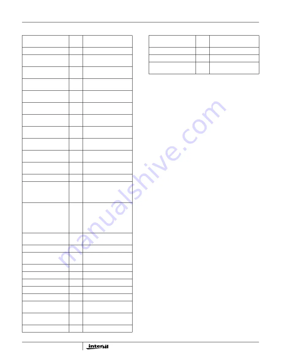
Appendix C Parts List
Appendix D HI5905 Theory of Operation
The HI5905 is a 14-bit fully differential sampling pipelined A/D
converter with digital error correction. Figure 17 depicts the
internal circuit for the converters front-end differential-in-
differential-out sample-and-hold (S/H). The sampling switches
are controlled by internal sampling clock signals which consist
of two phase non-overlapping clock signals,
φ
1 and
φ
2,
derived from the master clock (CLK) driving the converter.
During the sampling phase,
φ
1, the input signal is applied to
the sampling capacitors, C
S
. At the same time the holding
capacitors, C
H
, are discharged to analog ground. At the falling
edge of
φ
1 the input analog signal is sampled on the bottom
plates of the sampling capacitors. In the next clock phase,
φ
2,
the two bottom plates of the sampling capacitors are
connected together and the holding capacitors are switched to
the op amp output nodes. The charge then redistributes
between C
S
and C
H
, completing one sample-and-hold cycle.
The output of the sample-and-hold is a fully-differential,
sampled-data representation of the analog input. The circuit
not only performs the sample-and-hold function, but can also
convert a single-ended input to a fully-differential output for
the converter core. During the sampling phase, the V
IN
pins
see only the on-resistance of the switches and C
S
. The
relatively small values of these components result in a typical
full power input bandwidth of 100MHz for the converter.
As illustrated in the HI5905 Functional Block Diagram and
the timing diagram contained in Figure 18, three identical
pipeline subconverter stages, each containing a four-bit
flash converter, a four-bit digital-to-analog converter and an
amplifier with a voltage gain of 8, follow the S/H circuit with
the fourth stage being only a 4-bit flash converter. Each
converter stage in the pipeline will be sampling in one
phase and amplifying in the other clock phase. Each
individual sub-converter clock signal is offset by 180
degrees from the previous stage clock signal, with the
result that alternate stages in the pipeline will perform the
same operation. The output of each of the three identical
four-bit subconverter stages is a four-bit digital word
containing a supplementary bit to be used by the digital
error correction logic. The output of each subconverter
stage is input to a digital delay line which is controlled by
the internal clock. The function of the digital delay line is to
time align the digital outputs of the three identical four-bit
subconverter stages with the corresponding output of the
fourth stage flash converter before inputting the sixteen bit
result into the digital error correction logic. The digital error
REFERENCE
DESIGNATOR
QTY
DESCRIPTION
-
1
Printed Wiring Board
R16, R19
2
10
Ω
, 1/10W
805 Chip, 1%
R17, R18
2
499
Ω
, 1/10W
805 Chip, 1%
R13
1
56.2
Ω
, 1/10W
805 Chip, 1%
R14
1
A/R
Ω
, 1/10W
805 Chip, 1%
R15
1
22.1
Ω
, 1/10W
805 Chip, 1%
R2, R3
2
100
Ω
, 1/10W
805 Chip, 1%
R4, R12
2
0.0
Ω
, 1/4W
805 Chip, 5%
R5, R6
2
4.99k
Ω
, 1/10W
805 Chip, 1%
R7
1
49.9
Ω
, 1/10W
805 Chip, 1%
R8, R9, R10, R11, R20
5
249
Ω
, 1/10W
805 Chip, 1%
VR1
1
5k
Ω
Trim Pot
C5, C10, C12, C16, C18,
C22, C24, C27, C29, C31,
C33, C35, C39, C41, C42,
C44, C46
17
4.7
µ
F Chip Tant Cap,
10WVDC, 20%, EIA Case A
C1, C2, C4, C6, C7, C8,
C9, C11, C13, C14, C15,
C17, C20, C21, C23, C25,
C26, C28, C30, C32, C34,
C36, C37, C38, C40, C43,
C45, C47
28
0.1
µ
F Cer Cap, 50WVDC,
10%, 805 Case, Y5V
Dielectric
C3
1
A/R pF Cer Cap, 50WVDC,
10%, 805 Case
FB1-7
7
10
µ
H Ferrite Bead
J1, J2
2
SMA Straight Jack PCB
Mount
-
5
Protective Bumper
JP1
1
1x2 Header
JPH1
1
1x2 Header Jumper
P1
1
2x17 Header
TP1, 2, 3, 4
4
Test Point
U1
1
Intersil HI5905IN, 14-Bit 5
MSPS A/D Converter
U4
1
Ultrafast Voltage
Comparator
U2, U3
2
Octal D-type Flip-flop
U5, U6
2
Op-amp
U7
1
Hex Inverter
P2
64-Pin Eurocard RT Angle
Receptacle
REFERENCE
DESIGNATOR
QTY
DESCRIPTION
Application Note 9785


