


UH179TW
/
UH679TW
UDH179-02
20
S
ET
-U
P
P
ROCEDURES
UUU
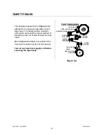
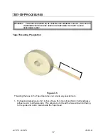
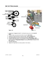
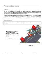
Tape Leg Length Adjustment
For optimum performance, the tape leg length has been factory set at 2 inches
(50 mm).
However, the tape leg length can be modified.
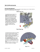
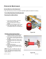
Front Tape Leg
To adjust the tape leg length on the
leading end of the box, refer to
Figure 7-12
of the clutch assembly.
Facing the rear main frame, loosen
the two (2) Flat Head Cap Screws
using a 3 & 4 mm hexagonal key.
Rotate the clutch assembly to bring
the lowers screw towards the minus
(-) sign stamped on the rear plate for
a shorter tape leg. Conversely, bring
the bottom screw towards the plus
(+) sign for a longer tape leg.
Re-tighten both Flat Head Cap
Screws.
Figure 7-10
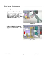
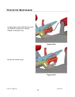
Rear Tape Leg
To adjust the tape leg length on the trailing
end of the box, both chrome knife arm
extension brackets must be re-positioned.
Unscrew the three (3) Flat Head Cap
Screws on each knife arm extension using
a 2.5 mm hexagonal key.
For a
UUU
Shorter Tape Leg
UUU
, bring the knife
arm towards the
UUU
front
UUU
of the tape head.
Conversely, for a
UUU
Longer Tape Leg
UUU
, bring
the knife arm towards the
UUU
rear
UUU
of the tape
head.
Replace the three (3) screws on each
knife arm extension and tighten.
Figure 7-11
Front
Rear
Содержание HSD2000-ET II MIRROR
Страница 1: ...HSD2000 ET II MIRROR Serial Numbers H179 or H679 XX X XXX TAPE HEAD ...
Страница 2: ...UH179TW UH679TW UDH179 02 2 ...
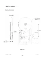
Страница 10: ...UH179TW UH679TW UDH179 02 10 SPECIFICATIONS UUUTape Head Dimensions Figure 6 1 ...
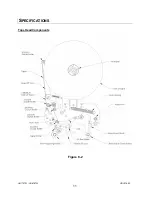
Страница 11: ...UH179TW UH679TW UDH179 02 11 SPECIFICATIONS UUUTape Head Components Figure 6 2 ...
Страница 41: ...41 THIS PAGE INTENTIONALLY BLANK ...
Страница 42: ...6 12 3 4 8 9 1 10 11 2 5 7 42 ...
Страница 44: ...7 8 9 11 6 12 7 8 7 8 9 10 3 5 2 4 1 44 MAIN FRAME ...
Страница 46: ...1 2 3 4 5 46 FRONT COVER FRAME ...
Страница 48: ...3 5 6 4 1 2 48 REAR COVER FRAME ...
Страница 50: ... 50 REAR ARM ...
Страница 52: ...11 1 15 13 14 10 2 4 5 6 9 12 8 2 3 7 13 13 10 8 CLUTCH ASSEMBLY ...
Страница 54: ... 54 MANDREL ASSEMBLY ...
Страница 56: ... 56 PEEL OFF ARM ASSEMBLY ...
Страница 58: ... 58 LINK ASSEMBLY ...
Страница 60: ...18 13 17 15 4 3 12 14 16 9 8 7 7 9 3 6 10 5 11 1 2 5 19 20 60 FRONT ARM ...
Страница 62: ...1 8 9 4 7 6 9 5 2 10 3 11 62 TAPE SHOE ASSEMBLY ...
Страница 64: ... 64 KNIFE ARM ...
Страница 66: ... 66 REPULSIVE PIVOT ASSEMBLY ...


