Section 9, Installing the Distribution Module
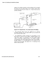
supply. The module contains a red and black wire to connect
this pump. The pre-heat switch on the remote control panel
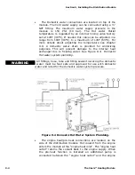
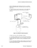
will activate this pump. See Figure 9-5: Engine heat/pre-heat
system plumbing.
Figure 9-5 Engine Heat / Pre-heat System Plumbing.
•
The pre-heat pump wires are capped off to prevent
accidental shorting. The pre-heat switch on the remote will
turn on power to the wires.
•
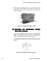
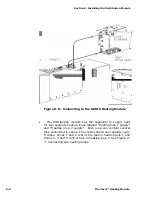
The Distribution module contains two connections on the
side panel to connect to the Oasis™ Heating Module. The
“Inlet from Heater” is connected to the hot coolant supply
outlet on the Oasis™ Heating Module. The “Outlet to Heater”
is connected to the cold coolant return inlet on the Oasis™
Heating Module. It is recommended to use minimal ¾” ID
hose for this connection. See Figure 9-6: Connecting to the
OASIS heating module.
International Thermal Research
9-5
Содержание Diesel and AC Heating System for Recreational Vehicles and Yachts
Страница 14: ...Section 1 Overview 1 8 The Oasis Heating Module...
Страница 20: ...Section 2 Mounting the Oasis Heating Module 2 6 The Oasis Heating Module...
Страница 28: ...Section 3 Installing the Exhaust System 3 8 The Oasis Heating Module...
Страница 32: ...Section 4 Installing the Fuel System 4 4 The Oasis Heating Module...
Страница 41: ......
Страница 48: ...Section 7 Plumbing the System 7 6 The Oasis Heating Module...
Страница 73: ......
Страница 74: ...9...
Страница 75: ...6 6 6 6 7K 8 0 7 4 7 4 7 8 9 7 8 9 7 8 9 7 8 9 D B 15C 8 D D H D 13 C 8 B B EC 8 D...
Страница 76: ...Section 9 Installing the Distribution Module 9 14 The Oasis Heating Module...

