2
Rev. 1.0
06/30/03
IRDC3073EVAL
www.irf.com
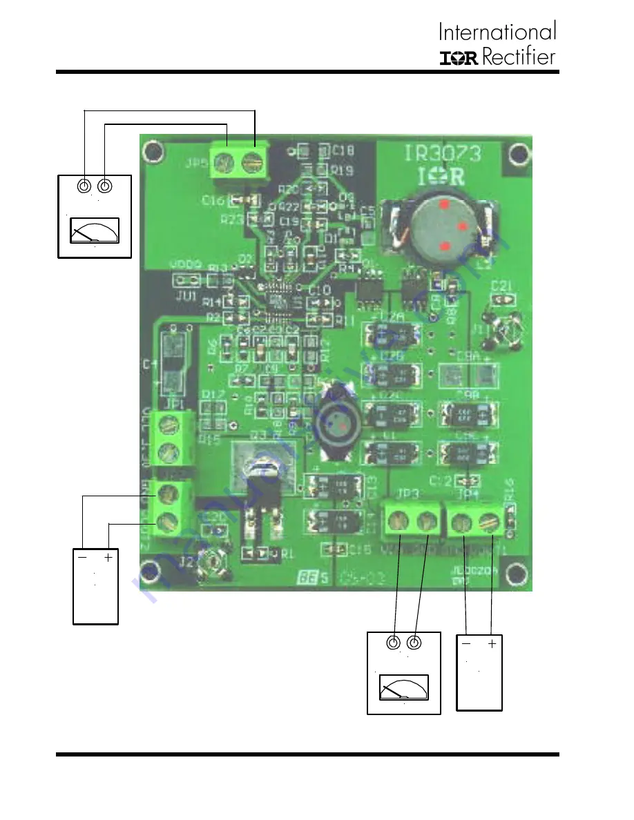
Figure 1 - Connection diagram of evaluation-board for IRU3073.
CONNECTION DIAGRAM
Power Supply
Gnd
+5V
10A Supply
+12V
1A Supply
Load2
2A
Load1
0 - 10A
Страница 1: ...age lockout for all input supplies an external programmable soft start function as well as output under voltage detection that latches off the device when an output short is detected Switcher VIN 5V V...
Страница 2: ...Rev 1 0 06 30 03 IRDC3073EVAL www irf com Figure 1 Connection diagram of evaluation board for IRU3073 CONNECTION DIAGRAM PowerSupply Gnd 5V 10A Supply PowerSupply Gnd 12V 1ASupply Load2 2A Load1 0 10...
Страница 3: ...located close to the MOSFETs All the decoupling capacitors and feedback components are located close to IC The feedback re sistors are tied to the output voltage at the point of regu lation The middl...
Страница 4: ...4 Rev 1 0 06 30 03 IRDC3073EVAL www irf com Figure 2 2 Middle layer 1 Figure 2 3 Middle layer 2 Figure 2 4 Bottom layer LAYOUT...
Страница 5: ...IRDC3073EVAL 5 Rev 1 0 06 30 03 www irf com Figure 3 Schematic of evaluation board for IRU3073 SCHEMATIC...
Страница 6: ...sistor Resistor Resistor Resistor Resistor Resistor Resistor Capacitor Diode Connector Scope Probe Spacer IRF7832 IRLR2703 IRU3073CQ BAT54 DO3316P 102 DO5022P 332HC 16TPB47M ECU V1H330JCV ECJ 2VF1E104...
Страница 7: ...ICS Figure 1 Normal condition at no load Ch1 HDrv Ch2 LDrv Ch4 Inductor Current Figure 2 Gate signals when SS pin pulls low Ch1 HDrv Ch2 LDrv Figure 3 Gate signals when SS pin pulls low Ch1 HDrv Ch2 L...
Страница 8: ...Visit us at www irf com for sales contact information Data and specifications subject to change without notice 02 01 TYPICAL OPERATING CHARACTERISTICS Figure 8 Load Transient Response PWM Section Figu...