NS3503-16P-4C L2/L4 Managed Giga Ethernet Switch Quick Installation Guide
3
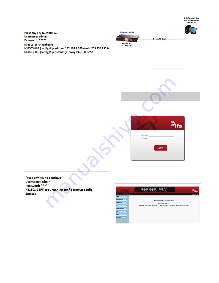
Figure 6-2: IP Address Screen
IP Address: 192.168.1.100
Subnet Mask: 255.255.255.0
Gateway: 192.168.1.254
3. Repeat Step 1 to check if the IP address has
changed.
If the IP is successfully configured, the Managed
Switch will apply the new IP address setting
immediately. You can access the Web interface of
the NS3503-16P Managed Switch through the new
IP address.
Note
:
If you are not familiar with console command or
the related parameter, enter “
?
” anytime in console to
get the help description.
7.
Saving the Configuration via the Console
In the switch, the running configuration file is stored in
the RAM. In the current version, the running
configuration sequence of running-config can be saved
from the RAM to FLASH by
writing
the command or
copying
the
running-config startup-config
command,
so that the running configuration sequence becomes the
startup configuration file, which is the configuration
saved.
1. At the “
NS3503-16P#
” prompt, enter
“
copy running-
config startup-config
” as shown in Figure 6-1.
Figure 7-1: The Configuration Screen
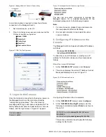
8. Starting Web Management
The following shows how to start up the
Web
Management
of the Managed Switch. Note the
Managed Switch is configured through an Ethernet
connection. Please make sure the manager PC must be
set to the same
IP subnet address
.
For example, the default IP address of the Managed
Switch is
192.168.0.100
, then the manager PC should
be set to
192.168.0.x
(where x is a number between 1
and 254, except 100), and the default subnet mask is
255.255.255.0.
Figure 8-1: IP Management Diagram
9. Logging in to the Managed Switch
1. Use Internet Explorer 8.0 or above Web browser
and enter IP address
http://192.168.0.100
to access
the Web interface.
2. When the following dialog box appears, please enter
the default user name and password “
admin
”. The
login screen in Figure 8-2 appears.
Default Username:
admin
Default Password:
admin
Figure 8-2: Login Screen
3. After entering the password, the main screen
appears as Figure 7-3 shows.
Figure 8-3: Web Main Screen of Managed Switch
The Switch Menu on the left of the Web page lets
you access all the commands and statistics the
Managed Switch provides.


