2 / 6
P/N 466-
5412 (EN) • REV A • ISS 15JAN18
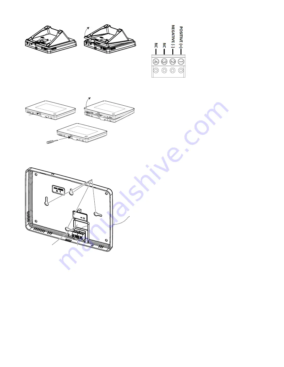
Figure 1: Desktop stand removal
2. Remove the touch screen from the mounting base
pressing the opening button on the bottom of the touch
screen (as shown in Figure 2). In case parts stick to each
other firmly, try to separate them by inserting a small
screwdriver into the opening slot beneath the protruding
opening button (Figure 2).
Figure 2: Opening slot
3. Feed the supplied power wire through the backside of the
wire drop in the mounting base (Figure 3).
Figure 3: Power Wire Routing in the Mounting Base
4. Connect the wire to the power terminals as identified in
Figure 4, taking particular care to ensure the
marked/dashed wire attaches to the Positive lead and the
unmarked wire attaches to the Negative lead. Observe
polarity by ensuring the same wire at the touch screen
mounting base is connected to the corresponding positive
and negative lead on the power supply. Do not use
different or longer run cable than the supplied wiring as
the DC power supply may not support it and intermittent
power failures in the touch screen may occur due.
Figure 4: Power connector
5. Reattach the touchscreen to the mounting base plate.
Angle the top of the touch screen into the tab hooks on the
top of the mounting base and swing the bottom of the
touch screen into the lower part of the mounting base until
you hear an audible click.
6. Connect the spaded ends of the power supply wire to the
terminal to the terminals on the power supply. Note: The
dashed line/writing side of the wire to positive. Ensure
consistency by wiring the + to + and
– to – as polarity must
be observed or touchscreen will not function. Plug in the
power, the touch screen will power up.
Learning
To program (learn) the touch screen into the Simon XT
panel:
1. Press the down arrow button on the panel and scroll to
System Programming.
2. Press OK.
The panel displays
Enter Code
.
3. Enter the installer access code and press OK.
4. Scroll to Sensors and press OK.
5. When the panel displays
Learn Sensor,
press OK.
The panel blinks
Trip Sensor nn
(where nn is the next
available zone number). You can enter a different zone
number if desired.
6. On the touch screen:
A. Press the Settings button (gear icon at bottom right).
B. Press the Down arrow until the Clear and Enroll
button appears.
C. Press the Clear and Enroll button. The touch screen
should indicate it is waiting for enrollment.
7. On the panel, you can now program the group number
(00, 01, 04, 05, 06, or 07) and press OK.
8. On the panel, press the Up or Down arrow to select a
name for the touch screen and press OK. (Refer to the
Simon XT installation instructions for programming sensor
text.)
You can select something simple, such as “Touch Pad”, or
use additional descriptors, such as “Bedroom Touch Pad”.
Opening
button
Terminal
block
Wires
Mounting
holes
Wire drop
opening


