Interface PCI-4302 Скачать руководство пользователя страница 34

PCI-4302

-31-

Interface Corporation

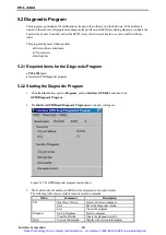
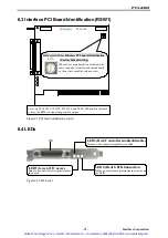
6.3 Interface PCI Board Identification (RSW1)

For every PCI-4301, PCI-4302, PCI-4304, and PCI-4304P board in the same
system, the RSW1 switch setting must be unique.

PCI-4302

Rotary switch for Interface PCI board identification

(Factory default setting)

When two or more boards are installed in the
same computer, set this switch on each board
so there is not a conflict with any other.

RSW1

Figure 6.1 PCI board identification switch
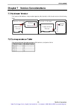
6.4 LEDs

CN1

LED1 (Green) I/O access

Blinks when an I/O access is generated for

this board.

LED3 (Red) Controller enabled/disabled

Turns on when controller capability is enabled.

LED4 (Red) GPIB transaction

Blinks when this board participates in activities on

the GPIB.

Figure 6.2 LED locator

Artisan Technology Group - Quality Instrumentation ... Guaranteed | (888) 88-SOURCE | www.artisantg.com

Содержание PCI-4302

Страница 1: ...ss underutilized and idle equipment along with credit for buybacks and trade ins Custom engineering so your equipment works exactly as you specify Critical and expedited services Leasing Rentals Demos...

Страница 2: ...Board Transfer rate 1 1 MB s max 1 channel DMA transfer mode Interface original controller LabVIEW compatible Transmission length Between equipment 4 m 13 12 ft max Total cable length 20 m 65 62 ft ma...

Страница 3: ...hange Interface Corporation does not assume the responsibility for compensation This product including its software may be used only in Japan Interface Corporation cannot be responsible for the use of...

Страница 4: ...s of software in Japanese version GPC 4301N deleted Format is revised 1 3 May 2005 Manual revised Manual title changed from PCI 4302 to MPB E4302 Warning of the CE Marking added Section 1 1 Packing Li...

Страница 5: ...uipment Failure to follow this warning may result in electric shock burns serious injury and in some cases even cause death Keep this PCI board away from flammable gases z Periodic Inspections The fol...

Страница 6: ...gth Limitation 22 4 2 3 Total Cable Length 22 4 2 4 Cabling Configurations 23 4 2 5 Address Assignment 23 4 2 6 Powered on Devices 23 4 3 Multiple GPIB Boards 24 Chapter 5 Troubleshooting and Diagnosi...

Страница 7: ...stem that has less than or equal to 10 devices 22 Figure 4 4 Total cable length for the system that has greater than 10 devices 22 Figure 5 1 The GPIB diagnostic program main window 26 Figure 6 1 PCI...

Страница 8: ...ng on which operating system is installed Refer to 4 1 Cabling in Difficult Situations page 25 if you have troubles in cabling How to run the utility programs Driver Software Parameter Configuration P...

Страница 9: ...o make sure of their addresses 2 1 Initializing the GPIB Interface Board The following steps show how to run the GPIB utility program and initialize the PCI 4302 1 When you have successfully installed...

Страница 10: ...hat you want to access Refer to 6 3 Interface PCI Board Identification RSW1 page 31 Type the GPIB address of the board in Primary Address By default this box has a value configured by the control pane...

Страница 11: ...60h through 7Eh IFC Interface clear The System Controller asserts the IFC line to initialize the bus The devices on the bus are unaddressed The System Controller becomes Controller in charge Controll...

Страница 12: ...when the TA indicator is turned on The TA indicator is turned on when the board becomes a Talker Click this button Specify the GPIB address in hexadecimal 2 Type a message to send to the Listener in t...

Страница 13: ...c button The LA indicator is turned on when this board becomes a Listener Specify the GPIB address in hexadecimal Select this button 2 Click the Recv button and then the received data will be displaye...

Страница 14: ...iffer depending on the GPIB devices Refer to those devices manuals The SRQ indicator is turned on when the GPIB devices request service The SRQ indicator is turned on when the GPIB devices request ser...

Страница 15: ...m and close the board click Close the Device on the File menu After closing the board click Exit on the File menu Glossary SRQ Service request A device asserts the SRQ line to request services from th...

Страница 16: ...ly according to your system 2 Make sure that the computer is turned off and the power cord is unplugged Remove the PC case cover and a slot cover 3 Insert the board into an open PCI slot Example Inser...

Страница 17: ...r to page 16 After the installation of the software is successfully completed configure the driver software parameters Refer to 3 8 Configuring the Driver Software Parameters page 18 3 4 1 Windows XP...

Страница 18: ...4 0 The driver may only be installed by a member of the System Administrators group 1 Log on to Windows NT 4 0 2 Insert the CD into your CD ROM drive 3 Right click the GPC4301 INF file in the GPF4301...

Страница 19: ...es such as I O addresses and interrupt request levels 3 4 6 Windows 95 1 When you log on to Windows 95 the device driver wizard will start automatically 2 Insert the CD into your CD ROM drive and then...

Страница 20: ...ms folder 3 6 Software Uninstallation 1 Click the Start button point to Settings and then click Control Panel 2 Double click Add Remove Programs and then click the Install Uninstall tab 3 Click Interf...

Страница 21: ...ard dialog box Remove Removes the selected board Default Settings Opens the Default Settings dialog box Close Closes this dialog box 3 Click Add on the Interface GPIB Board System Configuration dialog...

Страница 22: ...will appear b Configure parameters properly and then click OK Refer to Table 3 1 for more details Note After restarting your computer the changes are valid If you want to configure the board as Syste...

Страница 23: ...ut Specify an amount of time within the range of 1 through 65535 for waiting to detect events 100 100 ms GPIB command time out Specify an amount of time within the range of 1 through 65535 for the tim...

Страница 24: ...mm the cable may not clear the back panel If x is greater than or equal to 20 3 mm the cable connector may conflict with the next connector x must be less than 20 3 mm 20 3 mm x Side view of a connec...

Страница 25: ...the number of devices If the number of devices is greater than 10 the total length of cable is less than or equal to 20 0 meters For your convenience use the following expression to evaluate the accep...

Страница 26: ...ess Assignment A GPIB address consists of a primary address and a secondary address Assign a different primary address in the range of 0 through 30 or 00h through 1Eh to each interface in the system T...

Страница 27: ...d identification not to conflict with numbers assigned for other boards Refer to 6 3 Interface PCI Board Identification RSW1 page 31 Configuring driver software parameters Configure the driver softwar...

Страница 28: ...umber in the control panel applet Interface GPIB Board System Configuration in the Control Panel See 3 8 Configuring the Driver Software Parameters page 18 Register the board by using the control pane...

Страница 29: ...am 5 2 2 Starting the Diagnostic Program 1 Click the Start button point to Programs point to Interface GPF 4301 and then click GPIB Diagnostic Program 2 The Interface GPIB Board Diagnostic Program mai...

Страница 30: ...correctly initialize and configure the Interface GPIB boards Please inquire of our Technical Support Center about solutions for the unresolved problems 5 2 3 Checking the PCI Configuration and Other O...

Страница 31: ...e directory and file are created 4 Prepare formatted and blank floppy disks 5 Copy the files in the directory to the floppy disk prepared respectively 6 The installation disk for update is created Ref...

Страница 32: ...er capabilities 6 1 4 PCI Bus Master DMA Transfer The GPIB controller chip is capable of PCI bus master DMA transfer Using this capability significantly reduces software overheads at data transfer 6 1...

Страница 33: ...um data transfer length Total cable length less than or equal to 20 m Each cable assembly less than or equal to 4 m Number of devices 15 devices max GPIB I O connector IEEE Std 488 1 standard or equiv...

Страница 34: ...in the same computer set this switch on each board so there is not a conflict with any other RSW1 Figure 6 1 PCI board identification switch 6 4 LEDs CN1 LED1 Green I O access Blinks when an I O acces...

Страница 35: ...of a data message executes a parallel poll End or Identity DAV 6 Indicates data is enabled Data Valid NRFD 7 Indicates the device is ready or not ready to receive data Not Ready For Data NDAC 8 Indica...

Страница 36: ...of the board Component side of the board P xxx x xxx O Hardware version P xxx x xxx O Hardware version 106 68 174 63 mm 106 68 119 91 mm 7 2 Correspondence Table The version of the user s manual and...

Страница 37: ...lation 15 Driver software parameters 21 25 E Environmental specifications 2 H Hardware specifications 31 I I O connector 31 34 IEEE Std 488 1 30 IFC 8 9 Installation 14 15 L LED 30 32 Listener 9 10 30...

Страница 38: ...rious services listed below are provided on our Web site Product Information The latest information about our products specifications product selection guides etc Technical Support Online questions an...

Страница 39: ...MPB E4302 Ver 1 3 Vol 1 1 Artisan Technology Group Quality Instrumentation Guaranteed 888 88 SOURCE www artisantg com...

Страница 40: ...uipment Have surplus equipment taking up shelf space We ll give it a new home Learn more Visit us at artisantg com for more info on price quotes drivers technical specifications manuals and documentat...

Отзывы: