Service Manual
AT235
33
5.4 Attenuator test
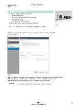
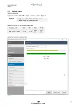
This test screen enables a manual check of all the input/output channels of the instrument. The screen is divided
into three sections, and must be used with utmost caution, as very high sound intensities can be reached.
Very high sound intensities can
be reached.
1. Output signals
In the signal output section, each of the output attenuators are controllable, enabling routing of the sound
to a specific output (i.e. headphones, probe speaker etc.).
•
Tone
switch ON/OFF
•
Pulse
ON/OFF
•
Stimuli frequency
The attenuator itself is divided into three sections (we refer to the block diagram for more information).
Test points 5, 6 and 7 enable testing of each part of the attenuator.
•
Max. output = damping 0 - Min. output = damping 120
•
Fixed attenuator level 0 = no damping - Level 25 = add 25 dB attenuation/damping.
•
+20 dB attenuation, ON/OFF, ON = add 20dB on top of 4 + 5
When damping is 20 dB or less the +20 box should be ticked. When damping is exactly 20 dB,
ticking the +20 box is optional. Above 20 dB damping, the box should remain empty.
2. Input Signals
In the signal input section, the functionality of an input can be verified. Via the dropdown menu the input
is selected. The slider enables control of the input attenuator’s amplification and the input level data on
the VU-meter.
3. Monitor / Talkback levels
This section verifies the functionality of the monitor / Talkback functionality. By changing position, control
of the levels is enabled.
Fig. 35
CAUTION

