Note:
(1) Please refer to the schematic diagram and install it step by step.
(2) All plugs, foot pads and shields have been installed before leaving the factory.
The swing arm, U-shaped clamp,
pedal tube and rear clamp seat have been assembled to form a swing rod assembly.
(3) When connecting parts with bolts and nuts, assemble them directly by hand. After all parts are assembled, use tools
to tighten them in place one by one when making final adjustment.
(4) Open the packing box, take out the parts and put them in different categories, and carry out the following
installation with reference to the installation diagram and parts list.
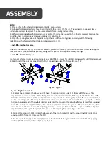
1.
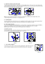
Install the rear bottom pipe
Install the rear
bottom
pipe
(2)
on
the
rear
connecting
plate
of
the
frame
(1)
with
two
sets
of semicircular head
square
neck bolts M
8
×
75(54), arc washer
ф
8 (52), spring washer
ф
8 (75
) and cap nut M10
(65). (see fig
.
1)
2.
Install the front bottom pipe
Use two sets of semicircular head square neck bolts M
8
×
75(54), arc washer
ф
8 (52), spring washer
ф
8 (75) and cap nut
M
8(65) to install the front foot pipe (2) on the front connecting plate of the frame (1). (see fig
.
2)
Figure 1 Figure 2
3
.
Installing front bracket
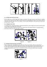
A.
Connect the terminal at the lower end of the eight-section trimmer body (19) firmly with the output fine
adjustment connecting line (18). (Note: firstly, turn the output trimmer knob all the way to the "
-
"direction (at this
time,
the connector terminal of the output trimmer body extends to the longest), tighten the connector terminal
on the connecting hook of the output trimmer connecting wire connector as shown in the figure, and pull it up hard
to clamp the upper end of the output trimmer body into the gr
oove of the adjusting frame. In case that the upper
end of the output fine adjustment body line cannot be just clamped into the groove of the adjusting frame, please
screw the nut at
the lower end of the adjusting frame to a proper position, so that the upper end of the output fine
adjustment body line
is just clamped into the groove of the adjusting frame. (see fig
.
4
-
A, b and c)
B.
Connect the sensor line 2(41) joint at the lower end of the front bracket (2) and the sensor line 1(42) joint at
the
upper end of the frame (1) firmly. (see fig
.
3-D)
C.
Set the front bracket (2) on the frame (1) and lock it with 6 sets of hexagon socket head bolts M8×16(56),
spring
washers ф 8 (75) and arc washers ф 8 (52). (see fig
.
3
-D)
Содержание IT-E240
Страница 1: ...IT E240 INTER TRACK Luxury Magnetic Elliptical Machine...
Страница 3: ......


