background image

950P 

Portable  Air Cleaning System


950P 

Portable Air Cleaning System


#10065


18


© Intellipure  2015


#10065


19


© Intellipure  2015


fig-6


fig-5


Maintenance 


Maintenance 


V-


BANK MAIN FILTER REPLACEMENT


Lock the (2) front wheels to secure the unit. 

(fig-1)


Remove the Filter Access Door located in the back of the unit using the four butterfly latches located on the 
sides of the unit. Lift the latch wings (4) and turn counter-clockwise to open. 

(fig-2)


Filter Access Door removal may require a firm pulling effort.


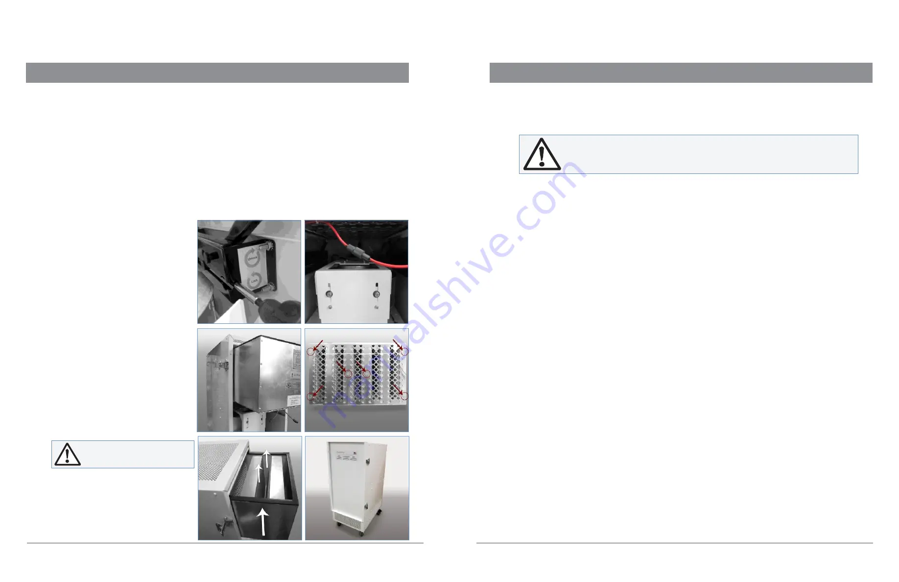
Using the Magnetic Bit Holder provided, alternate loosening the left and right Scissor Locking Mechanisms 
located near the motor plate in the filter. Make sure the Scissor Locking Mechanisms are fully opened. 

(fig-5)


Disconnect the High Voltage Lead from the High Energy Grid. 

(fig-6)


Using a firm pull, remove the V-Bank Main Filter and High Energy Grid Assembly out of the filter access 
opening. 

(fig-7)


Inspect and clean the inside of the unit. 
Refer to page 19 for proper instructions.


Separate the High Energy Grid from the 
V-Bank Main Filter by removing the


six screws (4 corners and 2 in the center) 
in the V-Bank Main Filter. 

(fig-8)


Replace the V-Bank Main Filter.


Secure the V-Bank Main Filter to the bottom 
of the High Energy Grid by using the


six screws (4 corners and 2 in the center) 
in the V-Bank Main Filter.


Slide the V-Bank Main Filter and High Energy 
Grid Assembly back into the unit. Pay 
attention to the Flow Direction Arrow on 
the Prefilter, the arrow should point 
upwards towards the Supply/Outlet  end


of the unit. 

(fig-9)


Using the Magnetic Bit Holder provided, 
alternate tightening the left and right 
Scissor Locking Mechanisms located 
near the motor plate in the filter.

CLEANING THE UNIT


Depending on contamination level, this procedure should be conducted about once a year or during each 
filter change or if an electrical problem occurs.


Remove the V-Bank Main Filter and High Energy Grid Assembly


Refer to page 18 for proper instructions.


To clean the wires, use a fiber free swab, either dry or moistened with distilled or deionized water, clean 
along the length of each wire, spring clip, and ceramic insulator.


Clean the inner surfaces of the High Energy Grid material using a lint cloth moistened with distilled or 
deionized water.


Clean the High Energy Grid surface by vacuuming between the wires using a small vacuum attachment or  
by using a lint free cloth, either dry or moistened with distilled or deionized water. Take care to avoid leaving 
large fibers snagged on the wires, control grid, or other components of the High Energy Grid.


Make sure that any contaminant that falls to the bottom of the filter unit is removed.


In extreme cases, it may be necessary to remove the wires from the springs attached at each end to the power 
distribution bars, thus allowing complete access to the inside of the High Energy Grid assembly for cleaning 
as previously described. It is recommended that the manufacturer be contacted for detailed instructions 
should this step appear  necessary.


Vacuum the bottom of the filter seal plate section and of the filter unit to remove any particles dislodged during 
cleaning. Reinstall the High Energy Grid, V-Bank Main Filter and Filter Access Door as previously instructed.


Reconnect the High Voltage Lead.


Ensure the Prefilter is firmly seated. 
The unit will not run if the Prefilter is 
not installed correctly.


Return the Filter Access Door. Lift the 
latch wings (4) and turn clockwise


to close. 

(fig-10)


fig-9


fig-10


Do not over-tighten the 

Scissor Lock Clamps.


Do not use alcohol or cleaners that may damage acrylics, plastics or aluminum.


fig-7


fig-8


Содержание 950P

Страница 1: ...Installation Manual 950P PORTABLE AIR CLEANING SYSTEM 2015 10065 ...

Страница 2: ...4 2 2amp FEATURES High Air Flow Capacity delivers high CFM with low energy consumption Wattage MobileDesign builtin3 5 safetylockswivelcasters fullwidth handle for easy movement Multiple Fan Speeds four fan speeds for ease of control 99 99 DFSFiltration Efficiency downtoasizeof0 007microns IndependentAirflow DistributionControl tofacilitate placement anywhere in the space Patented V Bank Filter in...

Страница 3: ... or disassembly by unauthorized personnel 5 defacing the serial number or 6 modifying the original factory assembled unit in any way B THIS LIMITED WARRANTY DOES NOT APPLY TO SHIPPING CHARGES FOR PRODUCT SHIPPED TO OR FROMTHEFACTORYORDESIGNATEDSERVICECENTERINCONNECTIONWITHWARRANTYCLAIMSNOR DOES IT APPLY TO ANY DAMAGES OCCURRING DURING SUCH SHIPMENT C This Limited Warranty does not apply to labor f...

Страница 4: ...the filtration system This manual contains general recommendations but specific requirements may apply to individual installations Such requirements are outlined in federal state and local codes Compliance with applicable codes and strict adherence to these installation instructions are the sole responsibility of the user This symbol will be used throughout this manual to indicate safety checkpoin...

Страница 5: ... Unit Description 11 Component Description 12 Installation Procedures 13 Power Requirements 13 Location Determination 13 System Operation 15 Electrical Connection 15 To Turn On the Unit 15 To Turn Off the Unit 15 Maintenance 17 Prefilter Replacement 17 VOC Post Filter Replacement 17 V Bank Main Filter Replacement 18 Cleaning the Unit 19 Parts List 20 Troubleshooting 21 DFS Troubleshooting Guide 22...

Страница 6: ...ier accepts the responsibility for any subsequent shortages or damage evident or concealed Inspection by the carrier of damage evident or concealed must be requested Evident shortage or damage should be noted on the carrier s delivery document before signature of acceptance Claims must be made against the carrier by the purchaser Filtration systems are shipped as fully assembled filter units STORA...

Страница 7: ...efilter is not installed correctly fig G Return the Filter Access Door Lift the latch wings 4 and turn clockwise to close fig H UNIT DESCRIPTION The 950PAir Cleaning System is a high performance system that utilizes patented award winning Disinfecting Filtration System technology DFS technology electrically enhances a low efficiency high flow low pressure drop filter to high efficiency while retai...

Страница 8: ...own to 007 microns once a year Replacement period depends on the level of pollution in the environment POWER REQUIREMENT The power requirements are as follows Electrical disconnects may also be required check local electrical codes Model Power FLA Power Usage Max Start up V Hz Phase AMPS WATTS 950P 120 50 60 1 4 44 590 950P 220 50 60 1 2 21 560 LOCATION DETERMINATION The 950P is designed as a port...

Страница 9: ...unction should also come on fig I TO TURN OFF THE UNIT To turn off the unit simply turn off the main switch located on the front of the unit Do not connect power to the unit until the High Energy Grid wires have been checked for proper connection Refer to page 10 fig I LO TURBO 950P REMOTE Each unit is also equipped with a Remote Control fig J The Remote has 3 buttons fig J ON SPEED Turns the unit...

Страница 10: ...lter is not installed correctly Return the Filter Access Door Lift the latch wings 4 and turn clockwise to close fig 2 VOC POST FILTER REPLACEMENT Lock the 2 front wheels to secure the unit fig 1 Remove the Filter Access Door located in the back of the unit using the four butterfly latches located on the sides of the unit Lift the latch wings 4 and turn counter clockwise to open fig 2 Filter Acces...

Страница 11: ...ending on contamination level this procedure should be conducted about once a year or during each filter change or if an electrical problem occurs Remove the V Bank Main Filter and High Energy Grid Assembly Refer to page 18 for proper instructions To clean the wires use a fiber free swab either dry or moistened with distilled or deionized water clean along the length of each wire spring clip and c...

Страница 12: ...the status of the fuses 2 If problem persists then check for disconnected wires or connectors inside the unit including all low voltage control connections 3 If the problem persists then call for assistance Blue LED FS is OFF Fan is not running 1 Check whether the unit is running on the required supply voltage and confirm the status of the fuses 2 If the problem persists check the prefilter and pr...

Страница 13: ...Bank Main Filter and ensure that it is free of metal debris excess dirt or hair etc G Secure the V Bank Main Filter to the High Energy Grid by using the six screws 4 corners and 2 in the center in the V Bank Main Filter H Stand the V Bank Main Filter and High Energy Grid Assembly up and inspect the gasket on the seal side of the Assembly Replace the gasket if it is damaged DFS TROUBLESHOOTING GUID...

Страница 14: ...950P Portable DFS Air Cleaning System 950P 220 10065 Intellipure 2015 1 1 950P ...

Страница 15: ... Intellipure 2015 10065 ...

Отзывы: