54 IM805 Operating Instructions Revision R032306
55
IM805 Operating Instructions Revision R032306
A p p e n d i x A
S t a n d a r d C o n n e c t i o n O p t i o n s
A p p e n d i x O v e r v i e w
The IM805 has multiple connection options available to the user. In gen-
eral, these options will not change the operational characteristics of the
driver. These connector options give the user multiple choices in how to
interface and mount the driver into a system. Listed below are the con-
nector options and how they may be used.
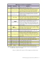
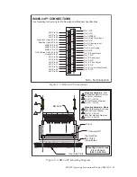
I M 8 0 5 - 3 4 P 1
The IM805-34P1 features the standard 8 pin terminal block at the connec-
tor P2 location. P1 has been replaced by a 34 pin header.
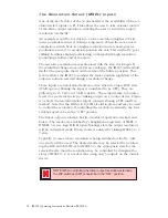
The typical use for this connector style is remote control of the micro-
step resolution select inputs. The advantages of this control method are
discussed later in this appendix.
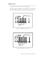
I M 8 0 5 - 8 P 2
This connector option uses 8 - 0.045 square pins at the P2 connector
location. The P1 connector location uses 8 -0.025 square pins.
This connector style would be advantageous in a scenario where the user
desiresto plug the IM805 directly into a system PCB.
NOTE:
When mounting the IM805 directly to a PCB by wire wrap or
receptacles, the Heat Sink temperature must still be kept at or below +70°
C.
I M 8 0 5 - 3 4 P 1 - 8 P 2
This option combines the features and potential uses of the IM805-34P1
and the IM805-8P2.
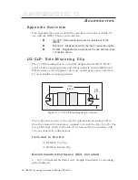
I M 8 0 5 - P L G
The IM805-PLG replaces both connectors P1 and P2 with an Altech 8
position pluggable interface. The removeable, plug-in screw terminal set
is available as an option (PLG-R).
This connector option is useful in system designs where ease of removal
is desired. For example, the IM805-PLG is pin compatible with the IM804/
5-PLG. If more power is needed the drives are easily swapped.


