Intelix Audisey REM-PACK-8 Скачать руководство пользователя страница 8

Intelix REM-PACK-8


Installation Manual 


8 www.intelix.com 


Connecting Power 

The following steps detail connecting power to the REM-PACK-8 system. 
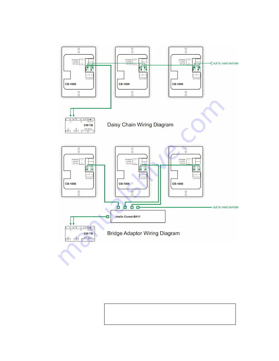
1)


Using a CW-TB from one of the CB-1000 remote control 
packages, connect the two conductor 18 gauge cable to the four 
conductor phoenix-style wiring block. The conductor connected to 
the (-) block on the remote controls should be connected to the (-) 
block on the CW-TB. The conductor connected to the (+) block on 
the remote controls should be connected to the (+) block on the 
CW-TB. Connect the wiring block to the physical CW-TB. 


Warning 

Do not reverse power on the CW-TB and CB-1000 remote 
controls. The system does not provide diode protection.  

Содержание Audisey REM-PACK-8

Страница 1: ...Audisey REM PACK 8 by Intelix...

Страница 2: ...isted Pair and 18 Gauge Cable 5 Preparing the Serial Cable 6 9 Wiring with Twisted Pair Cable 10 Programming the REM PACK 8 Remotes 15 Installing Athena Designer Software 16 Customizing the Physical R...

Страница 3: ...button remote controls needed for 2 16 independent zones Each remote control mounts into a standard single gang wallbox and features visual and auditory feedback multiple label options and password p...

Страница 4: ...ote controls to be located up to 230 feet from the controlled hardware The main advantage of wiring according to Cabling Schematic A is system distance because only data is being transmitted over the...

Страница 5: ...d 4 Terminate one pair two conductors of the twisted pair cable to the three conductor phoenix style wiring block One conductor should be in the far left slot and one conductor should be in the far ri...

Страница 6: ...ble GND should be connected to the phoenix style style connecter conductor 3 GND on the ION LT 3 Mount a CW TB wiring block found in each of the CB 1000 remote control packages in a permanent location...

Страница 7: ...000 remote controls should be connected to the CW TB the CW TB should be connected to the ION LT and the ION LT should be connected to the controlled hardware 6 Optional The CB 1000 remote controls ma...

Страница 8: ...gauge cable to the four conductor phoenix style wiring block The conductor connected to the block on the remote controls should be connected to the block on the CW TB The conductor connected to the b...

Страница 9: ...Main Power input on the CW TB 3 Plug in the power supply 4 The remote controls are now powered and should illuminate 5 Next connect a 12VDC power supply to the ION LT located near the controlled hardw...

Страница 10: ...air two conductors of the twisted pair cable to the three conductor phoenix style wiring block One conductor should be in the far left slot and one conductor should be in the far right slot Connect th...

Страница 11: ...ble GND should be connected to the phoenix style style connecter conductor 3 GND on the ION LT 3 Mount a CW TB wiring block found in each of the CB 1000 remote control packages in a permanent location...

Страница 12: ...r on the CB 1000 remote to the power conductor on the CW TB iii Connect the IR conductor on the CB 1000 remote to the IR conductor on the CW TB iv Connect the IR conductor on the CB 1000 remote to the...

Страница 13: ...an RJ45 bridge adaptor such as the Intelix Comet BA11 or Comet BA4 is used sold separately The bridge adaptor splits an RJ45 terminated cable to multiple outputs and is installed between the CW TB an...

Страница 14: ...input on the CW TB 2 Plug in the power supply 3 The remote controls are now powered and should illuminate 4 Next connect a 12VDC power supply to the ION LT located near the controlled hardware 5 Plug...

Страница 15: ...signer Software Begin by determining which remote and which button you are working with The remotes should have arrived pre labeled as remote 1 remote 2 remote 3 remote 4 remote 5 remote 6 remote 7 an...

Страница 16: ...t dropdown Note that there may be a short delay while the software and physical hardware toggle settings Installing Athena Designer Software Athena Designer Software is located on the Athena Designer...

Страница 17: ...e control 1 will be tied to output 1 zone 1 remote control 2 will be tied to output 2 zone 2 etc 6 Repeat step 5 for each button on each remote you wish to configure When finished select Close You hav...

Страница 18: ...rew the decora faceplate 5 Remove the white plastic button holder by squeezing the two white tabs on the back of the circuit board 6 Once the white plastic holder has been removed the buttons should b...

Страница 19: ...the Diagnostics dropdown and Communication Diagnostics The Communications Diagnostics screen will open 5 Select Connect Messaging should appear in the Message Buffer window You are now connected to t...

Страница 20: ...4 25 H x 2 38 W x 1 25 D CB 1000 Form Factor Single gang decora Regulatory UL RoHS CB 1000 Feedback Audible button click button backlighting CB 1000 Security Built in passcode Power Supplies 12VDC CB...

Страница 21: ...tion on installing and programming the Audisey Athena matrix mixer amplifier please consult the Audisey Installation and User Manual Should you have questions or require assistance while installing th...

Страница 22: ...ecified in the user manual 2 Installation specific wiring 3 Malfunction resulting from abuse or misuse of the product 4 Exterior chassis appearance 5 Malfunction occurring after repairs have been made...

Страница 23: ...We appreciate your business Please contact us with your questions and comments Intelix 2222 Pleasant View Road Suite 1 Middleton WI 53562 Phone 608 831 0880 Toll Free 866 4 MATMIX Fax 608 831 1833 ww...

Отзывы: