background image


20  

Intel

®

 Storage System SSR316MJ2 Backplane Board 

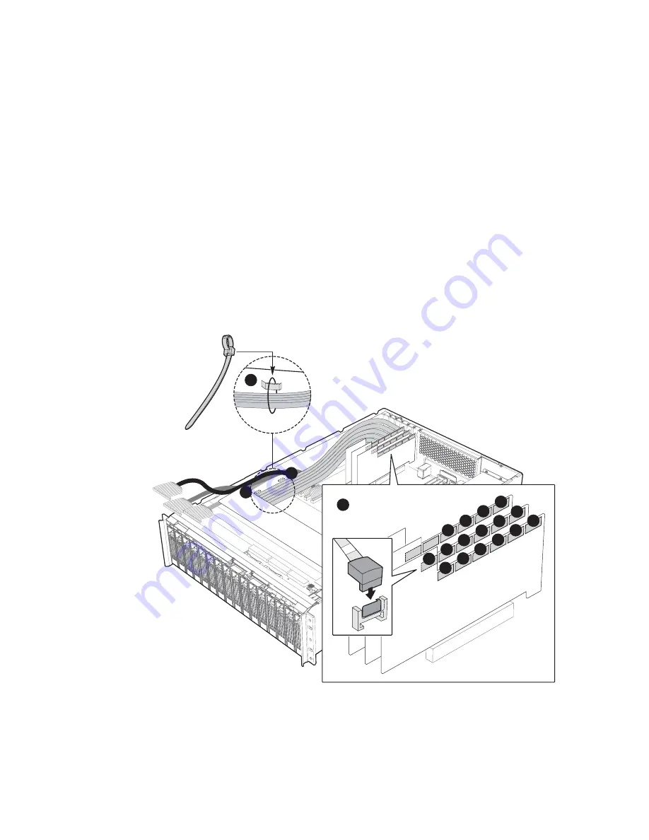
Re-connect SATA Cables to HBA Cards 


A.


Carefully re-connect the 16 SATA Cable connectors to the three SATA Host Bus Adapter 
Cards. Ensure that the SATA Cables are routed to the outside of the Host Bus Adapter 
Cards. See Figure 13.  

B.


Insert new plastic cable ties through the steel links on the side of the chassis where the 
SATA Cables are normally routed. Bundle the SATA Cables in the same way they were 
originally bundled and snap the ties tight into place around the cables. Wrap new plastic 
cable ties around the SATA Cables in the other spots where the original plastic cable ties 
were cut, and snap the ties tight into place around the cables. See Figure 13. A total of 
seven new plastic cable ties should be used. Route the SATA Cables along the side of the 
chassis in the same way that the original SATA Cables were routed. The cables remain on 
the chassis side of the Host  Bus Adapter Cards and connect to the cards from the chassis 
side.  


B

B

B

0

1

2

3

4

5

6

7

8

9

10

11

12

13

14

15

A


Figure 13.


Re-connecting the SATA Cables to the HBA Cards  

Содержание SSR316MJ2

Страница 1: ...Intel Storage System SSR316MJ2 Backplane Board FMJBACKPLANE Installation Guide Order Number C75951 001...

Страница 2: ...s en garde indiqu es dans ce document avant de suivre toute instruction Consultez Intel Server Boards and Server Chassis Safety Information rendez vous sur le site http support intel com support mothe...

Страница 3: ...maximum of 1900 BTUs per hour for a fully loaded Intel Storage System SSR316MJ2 Disclaimer Information in this document is provided in connection with Intel products No license express or implied by...

Страница 4: ...les from the Host Bus Adapter Cards 13 Cut the Plastic Ties that House the SATA Cables 14 Remove I2 C Cables from Backplane Board 15 Remove Power Distribution Board Module Connectors from Backplane Bo...

Страница 5: ...d Module Connectors 16 Figure 10 Removing the Backplane Board from the System 17 Figure 11 Installing the New Backplane Board in the System 18 Figure 12 Re Connecting the Power Distribution Board Modu...

Страница 6: ...vi Intel Storage System SSR316MJ2 Backplane Board...

Страница 7: ...l the FMJBACKPLANE Backplane Board into the Intel Storage System SSR316MJ2 The FMJBACKPLANE Backplane Board is installed into the storage system just behind the hard disk drives near the front portion...

Страница 8: ...and Remove Chassis Cover A From within the Intel Storage System Console power down your system B Remove both AC Power cords from the AC Power inputs on your system See Figure 1 C Loosen the two thumb...

Страница 9: ...andles downward See Figure 2 C Slide the hard disk drives and hard disk drive carriers at least halfway out of the hard disk drive bays See Figure 2 It is not necessary to completely remove the hard d...

Страница 10: ...ard See Figure 3 B Remove the Secondary IDE Cable labeled J3 from its receptacle on the front panel board See Figure 3 C Remove the Front Panel Cable labeled J1 from its connector receptacle on the fr...

Страница 11: ...Assembly A Using a Number 1 size Phillips Screwdriver remove the Phillips screw on each side of the system that holds the system fan assembly in place See Figure 4 Set these screws aside They will be...

Страница 12: ...eboard A Remove the wire connector for Fan 3 from the baseboard See Figure 5 B Remove the wire connector for Fan 4 from the baseboard See Figure 5 C Remove the wire connector for Fan 5 from the basebo...

Страница 13: ...ll up on both sides of the system and remove the fan assembly from the storage system Set the system fan assembly on a static free surface See Figure 6 B Carefully remove the 16 SATA Cable connectors...

Страница 14: ...e System SSR316MJ2 Backplane Board Cut the Plastic Ties that House the SATA Cables A Cut the plastic cable ties that bundle the SATA Cables See Figure 7 A Figure 7 Cutting the Plastic Ties that House...

Страница 15: ...2J6 from its I2 C Cable header in the HBA Card set See Figure 8 B Carefully remove the I2 C Cable connector labeled JP6 from its I2 C Cable header on the backplane board Carefully remove the I2 C Cabl...

Страница 16: ...emove Power Distribution Board Module Connectors from Backplane Board A Carefully remove the two 12 pin Power Distribution Board Module connectors from the backplane board See Figure 9 A Figure 9 Remo...

Страница 17: ...Figure 10 Set these screws aside They will be re installed later B Using a Number 1 size Phillips Screwdriver remove the four Phillips screws from the steel lip that holds the backplane board in place...

Страница 18: ...n the screw holes on the backplane board with the screws holes on the steel lip Using a Number 1 size Phillips Screwdriver screw in the four Phillips screws into the steel lip and the backplane board...

Страница 19: ...ect Power Distribution Board Module Connectors to Backplane Board A Carefully re connect the two 12 pin Power Distribution Board Module connectors to the backplane board See Figure 12 A Figure 12 Re C...

Страница 20: ...were originally bundled and snap the ties tight into place around the cables Wrap new plastic cable ties around the SATA Cables in the other spots where the original plastic cable ties were cut and s...

Страница 21: ...e Figure 14 B Carefully re connect the I2 C Cable connector labeled JP6 to its header on the backplane board Carefully re connect I2 C Cable connector labeled SL3J6 to its header in the HBA Card set S...

Страница 22: ...ires away from the space that is occupied by the system fan assembly Align the holes on the bottom edge of the system fan assembly with the blue plastic brackets on the bottom of the chassis Move the...

Страница 23: ...n Assembly to System A Using a Number 1 size Phillips Screwdriver screw in the one Phillips screw on each side of the system into place until the system fan assembly is mounted in the chassis See Figu...

Страница 24: ...seboard A Re connect the wire connector for Fan 3 to the baseboard See Figure 17 B Re connect the wire connector for Fan 4 to the baseboard See Figure 17 C Re connect the wire connector for Fan 5 to t...

Страница 25: ...J5 into its receptacle on the front panel board See Figure 18 D Re seat the front panel power connector into its receptacle on the front panel board See Figure 18 NOTE The color of the mesh sheath of...

Страница 26: ...seat all sixteen hard disk drives in the hard disk drive bays located on the front of the system Slide all sixteen drives into the bays as far as they can go See Figure 19 B Use the handles to lock t...

Страница 27: ...lot Push the top cover forward until it reaches the front of the system See Figure 20 B Tighten the two thumb screws on the back of the chassis cover See Figure 20 C Re attach the AC power cables See...

Страница 28: ...28 Intel Storage System SSR316MJ2 Backplane Board...

Отзывы: