background image

True Scale Fabric Adapter Hardware

July 2015

Installation Guide

Order Number: G91929004US

17

Adapter Hardware

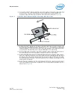
into the slot. Be careful not to push, grab, or put pressure on any other part of the 

card, and avoid touching any of the components. 

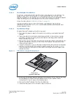
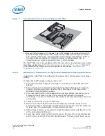
8. Secure the face plate to the chassis. The Intel

®

 adapter has a screw hole on the 

side of the face plate that can be attached to the chassis with a retention screw. 

The securing method may vary depending on the chassis manufacturer. Refer to 

the system documentation for information about mounting details such as 

mounting holes, and screws to secure the card or other brackets.

Next, install the cables, as described in 

“Cabling the Adapter to the Switch” on page 17

Then test your installation by powering up the system (see 

“Completing the 

Installation” on page 17

).

3.5

Switch Configuration and Monitoring

The Intel interconnect is designed to work with all InfiniBand

*

-compliant switches, such 

as the the Intel

®

 12000 series. Follow the applicable switch documentation for 

installing and configuring your switches.

3.6

Cabling the Adapter to the Switch

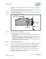
Follow the recommendations of your cable vendor for cable management and proper 

bend radius.

The QLE7340 and QLE7342 are cabled the same way. 

To install the cables:

1. Check that you have removed the protector plugs from the cable connector ends. 
2. Different vendor cables might have different latch mechanisms. Determine if your 

cable has a spring-loaded latch mechanism.

• If your cable is spring-loaded, grasp the metal shell and pull on the plastic latch to 

release the cable. To insert, push and the cable snaps into place. You will hear a 

short “click” sound from the cable connector when it snaps in.

• If your cable latch mechanism is not spring-loaded, push on the metal case, then 

push the plastic latch to lock the cable in place. 

3. The InfiniBand

*

 cables are symmetric; either end can be plugged into the switch. 

Connect the cable to the connector on the Intel

®

 QLE7340 and QLE7342. Depress 

the side latches of the cable when connecting. (On some cables, this latch is 

located at the top of the cable connector.) Make sure the lanyard handle on the 

cable connector is slid forward toward the card connector until fully engaged.

4. Connect the other end of the cable to the switch.

3.7

Completing the Installation

To complete the hardware installation:

1. Complete any other installation steps for other components. 
2. Replace the cover plate and back panel.
3. Verify that the power cable is properly connected.
4. Turn on the power supply and boot the system normally.
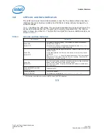
5. Watch the LED indicators. The LEDs will flash only once, briefly, at power-up. The 

LEDs are functional only after the True Scale software has been installed, the driver 

has been loaded, and the system is connected to an InfiniBand

*

 switch. To use the 

LEDs to check the state of the adapter, see 

“LED Link and Data Indicators”

.

Содержание QLE7340

Страница 1: ...Order Number G91929004US True Scale Fabric Adapter Hardware Installation Guide July 2015 ...

Страница 2: ...RY OR DEATH ARISING IN ANY WAY OUT OF SUCH MISSION CRITICAL APPLICATION WHETHER OR NOT INTEL OR ITS SUBCONTRACTOR WAS NEGLIGENT IN THE DESIGN MANUFACTURE OR WARNING OF THE INTEL PRODUCT OR ANY OF ITS PARTS Intel may make changes to specifications and product descriptions at any time without notice Designers must not rely on the absence or characteristics of any features or instructions marked rese...

Страница 3: ... the Package Contents 12 3 3 2 List of the Package Contents 12 3 3 3 Unpacking the Intel Adapter 13 3 4 Hardware Installation 13 3 4 1 Hardware Installation for QLE734x with PCI Express Riser 13 3 4 1 1 Dual Adapter Installation 14 3 4 1 2 Installation Steps 14 3 4 2 Hardware Installation for QLE734x Without a PCI Express Riser 16 3 5 Switch Configuration and Monitoring 17 3 6 Cabling the Adapter ...

Страница 4: ...4 Order Number G91929004US Date Revision Description May 2013 001US Initial release January 2014 002US Updated document File Info meta data August 2014 003US Update Support link in Section 1 7 Technical Support on page 7 July 2015 004US Document revision incremented for release 7 4 ...

Страница 5: ...1 2 How this Guide is Organized The Intel Adapter Hardware Installation Guide is organized into these sections Chapter 1 0 Introduction contains an overview of the host channel adapters and software describes interoperability with other products lists all related documentation and provides Intel contact information Chapter 2 0 Hardware Installation Checklist provides a high level overview of the h...

Страница 6: ...formation Caution indicates the presence of a hazard that has the potential of causing damage to data or equipment Warning indicates the presence of a hazard that has the potential of causing personal injury Text in blue font indicates a hyperlink jump to a figure table or section in this guide and links to Web sites are also shown in blue For example Table 2 lists problems related to the user int...

Страница 7: ...identify related topics either within this manual or in the online help throughout this document 1 6 License Agreements Refer to the Intel Software End User License Agreement for a complete listing of all license agreements affecting this product 1 7 Technical Support Intel True Scale Technical Support for products under warranty is available during local standard working hours excluding Intel Obs...

Страница 8: ...Adapter Hardware True Scale Fabric Adapter Hardware Installation Guide July 2015 8 Order Number G91929004US ...

Страница 9: ...your platform See Table 1 2 Check to see that you have the appropriate cables and switches as described in Cabling and Switches on page 11 3 Following the safety instructions in Safety with Electricity on page 12 Unpack the adapter Unpacking Information on page 12 and verify the package contents 4 Install the adapter by following the instructions in Hardware Installation on page 13 5 Cable the ada...

Страница 10: ...Adapter Hardware True Scale Fabric Adapter Hardware Installation Guide July 2015 10 Order Number G91929004US ...

Страница 11: ...1 This device may not cause harmful interference and 2 this device must accept any interference received including interference that may cause undesired operations Different adapters work on different platforms Table 1 shows the relationship between the adapter model and different types of motherboards Installation of the QLE7340 QLE7342 in a 1U or 2U chassis requires the use of a riser card See F...

Страница 12: ...er is not active Power off all attached devices such as monitors printers and external components Note that many motherboards and power supplies maintain standby power at all times Inserting or removing components while standby is active can damage them Use normal precautions to prevent electrostatic discharge which can damage integrated circuits 3 3 Unpacking Information This section provides ins...

Страница 13: ...g Handle the adapter only by its edges or the face plate Do not allow the adapter or any of its components to touch any metal parts 3 After checking for visual damage store the adapter and the riser card in their anti static bags until you are ready to install them 3 4 Hardware Installation This section contains hardware installation instructions for the QLE7340 and QLE7342 3 4 1 Hardware Installa...

Страница 14: ...e Intel adapter 2 Take precautions to avoid electrostatic damage ESD to the cards by properly grounding yourself or touching the metal chassis to discharge static electricity before handling the cards 3 Remove the cover screws and cover plate to expose the system s motherboard For specific instructions on how to do this follow the hardware documentation that came with your system 4 Locate the PCIe...

Страница 15: ...in the next step 10 Turn the assembly so that the riser card connector edge is facing the PCIe slot on the motherboard and the face plate is toward the front of the chassis 11 Holding this assembly above the motherboard at about a 45 degree angle slowly lower it so that the connector on the face plate clears the blanking panel opening of the chassis from the inside Slowly align the connector edge ...

Страница 16: ...out a riser card 1 Shut down the power supply to the system into which you will install the Intel adapter 2 Take precautions to avoid electrostatic discharge ESD damage to the cards by properly grounding yourself or touching the metal chassis to discharge static electricity before handling the cards 3 If you are installing the Intel adapter into a covered system remove the cover screws and cover p...

Страница 17: ...nds 2 Different vendor cables might have different latch mechanisms Determine if your cable has a spring loaded latch mechanism If your cable is spring loaded grasp the metal shell and pull on the plastic latch to release the cable To insert push and the cable snaps into place You will hear a short click sound from the cable connector when it snaps in If your cable latch mechanism is not spring lo...

Страница 18: ...d Loss of signal Verify that the software is installed and configured with ipath_control i If correct check both cable connectors Green ON Amber OFF Signal detected and the physical link is up Ready to talk to SM to bring the link fully up If this state persists the SM may be missing or the link may not be configured Use ipath_control i to verify the software state If all host channel adapters are...

Отзывы: