Product Description
11
1.1.2
Board Layout
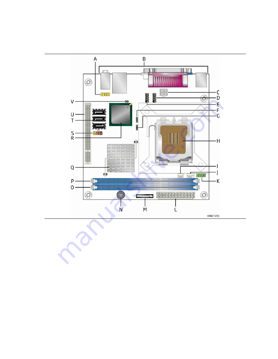
Figure 1 shows the location of the major components.
Figure 1. Major Board Components
Table 2 lists the components identified in Figure 1.
Страница 1: ...contain design defects or errors known as errata that may cause the product to deviate from published specifications Current characterized errata are documented in the Intel Desktop Board DG41MJ Specification Update Intel Desktop Board DG41MJ Technical Product Specification ...
Страница 2: ...t relate to the presented subject matter The furnishing of documents and other materials and information does not provide any license express or implied by estoppel or otherwise to any such patents trademarks copyrights or other intellectual property rights Intel may make changes to specifications and product descriptions at any time without notice Designers must not rely on the absence or charact...
Страница 3: ...t Contains Chapter Description 1 A description of the hardware used on the board 2 A map of the resources of the board 3 The features supported by the BIOS Setup program 4 A description of the BIOS error messages beep codes and POST codes 5 Regulatory compliance and battery disposal information Typographical Conventions This section contains information about the conventions used in this specifica...
Страница 4: ...bits KB Kilobyte 1024 bytes Kbit Kilobit 1024 bits kbits sec 1000 bits per second MB Megabyte 1 048 576 bytes MB sec Megabytes per second Mbit Megabit 1 048 576 bits Mbit sec Megabits per second xxh An address or data value ending with a lowercase h indicates a hexadecimal value x x V Volts Voltages are DC unless otherwise specified This symbol is used to indicate third party brands and names that...
Страница 5: ...face 22 1 9 Audio Subsystem 22 1 9 1 Audio Subsystem Software 23 1 9 2 Audio Connectors and Headers 23 1 10 LAN Subsystem 24 1 10 1 LAN Subsystem Software 24 1 10 2 RJ 45 LAN Connector with Integrated LEDs 25 1 11 Hardware Management Subsystem 26 1 11 1 Hardware Monitoring and Fan Control 26 1 11 2 Fan Monitoring 26 1 11 3 Chassis Intrusion and Detection 26 1 11 4 Thermal Monitoring 27 1 12 Power ...
Страница 6: ...6 2 Custom Splash Screen 61 3 7 BIOS Recovery 61 3 8 Boot Options 62 3 8 1 CD ROM Boot 62 3 8 2 Network Boot 62 3 8 3 Booting Without Attached Devices 62 3 8 4 Changing the Default Boot Device During POST 62 3 9 Adjusting Boot Speed 63 3 9 1 Peripheral Selection and Configuration 63 3 9 2 BIOS Boot Optimizations 63 3 10 BIOS Security Features 64 4 Error Messages and Beep Codes 4 1 Speaker 65 4 2 B...
Страница 7: ... 22 5 LAN Connector LED States 25 6 Effects of Pressing the Power Switch 28 7 Power States and Targeted System Power 29 8 Wake up Devices and Events 30 9 System Memory Map 37 10 Component side Connectors and Headers Shown in Figure 10 41 11 Serial ATA Connectors 42 12 Chassis Intrusion Header 42 13 Serial Port Header 42 14 Front Chassis Fan Header 42 15 Processor Fan Header 42 16 Front Panel Audio...
Страница 8: ...n Keys 58 32 Acceptable Drives Media Types for BIOS Recovery 61 33 Boot Device Menu Options 62 34 Supervisor and User Password Functions 64 35 Beep Codes 65 36 BIOS Error Messages 65 37 Port 80h POST Code Ranges 66 38 Port 80h POST Codes 67 39 Typical Port 80h POST Sequence 70 40 Safety Standards 71 41 Lead Free Board Markings 76 42 EMC Regulations 77 43 Product Certification Markings 78 ...
Страница 9: ... Controller Hub ICH7 Video Intel Graphics Media Accelerator X4500 Intel GMA X4500 onboard graphics subsystem Audio 5 1 2 channel audio subsystem using the Realtek ALC888VC audio codec Legacy I O Control Winbond W83627DHG P based Legacy I O controller for hardware management serial parallel and PS 2 ports Peripheral Interfaces Eight USB 2 0 ports four back panel connectors and two front panel heade...
Страница 10: ...Summary continued Expansion Capabilities One PCI Conventional bus connector Hardware Monitor Subsystem Voltage sense to detect out of range power supply voltages Thermal sense to detect out of range thermal values Two fan headers Two fan sense inputs used to monitor fan activity ...
Страница 11: ...Product Description 11 1 1 2 Board Layout Figure 1 shows the location of the major components Figure 1 Major Board Components Table 2 lists the components identified in Figure 1 ...
Страница 12: ...anel USB header F BIOS Setup configuration jumper block G Auxiliary front panel power LED header H LGA775 processor socket I Front chassis fan header J Processor fan header K Serial port header L Main Power connector 2 X 12 M Battery N Speaker O DIMM Channel B socket P DIMM Channel A socket Q Intel 82G41 GMCH R Intel 82801GB I O Controller Hub ICH7 S Front panel header T Serial ATA connectors 3 U ...
Страница 13: ...Product Description 13 1 1 3 Block Diagram Figure 2 is a block diagram of the major functional areas Figure 2 Block Diagram ...
Страница 14: ...ory http support intel com support motherboards desktop sb CS 025414 htm Integration information http www intel com support go buildit 1 4 Processor The board is designed to support the following processors Intel Celeron processor in an LGA775 socket Intel Xeon processor in an LGA775 socket Intel Core 2 Duo processor in an LGA775 socket Intel Pentium Dual Core processor in an LGA775 socket Intel C...
Страница 15: ...Ms with SPD timings of only 5 5 5 or 6 6 6 tCL tRCD tRP NOTE To be fully compliant with all applicable DDR SDRAM memory specifications the board should be populated with DIMMs that support the Serial Presence Detect SPD data structure This enables the BIOS to read the SPD data and program the chipset to accurately configure memory settings for optimum performance If non SPD memory is installed the...
Страница 16: ...al world applications This mode is used when only a single DIMM is installed or the memory capacities are unequal Technology and device width can vary from one channel to the other If different speed DIMMs are used between channels the slowest memory timing will be used Flex mode This mode provides the most flexible performance characteristics The bottommost DRAM memory the memory that is lowest w...
Страница 17: ...e memory channel and DIMM configuration Figure 3 Memory Channel Configuration and DIMM Configuration INTEGRATOR S NOTE Regardless of the memory configuration used dual channel single channel or flex mode DIMM 0 of Channel A must always be populated ...
Страница 18: ...products desktop chipsets index htm Resources used by the chipset Chapter 2 1 6 1 Intel G41 Graphics Subsystem The Intel G41 Express chipset contains two separate mutually exclusive graphics options Either the Intel Graphics Media Accelerator X4500 Intel GMA X4500 graphics controller contained within the 82G41 GMCH is used or a PCI graphics card can be used When a PCI graphics card is installed th...
Страница 19: ...nstalled DVMT returns system memory back to the operating system when the additional system memory is no longer required by the graphics subsystem DVMT will always use a minimal fixed portion of system physical memory as set in the BIOS Setup program for compatibility with legacy applications An example of this would be when using VGA graphics under DOS Once loaded the operating system and graphic...
Страница 20: ...retical maximum transfer rate of 3 Gbits sec per port One device can be installed on each port for a maximum of three Serial ATA devices A point to point interface is used for host to device connections unlike Parallel ATA IDE which supports a master slave configuration and two devices per channel For compatibility the underlying Serial ATA functionality is transparent to the operating system The ...
Страница 21: ...not be accurate Replace the battery with an equivalent one Figure 1 on page 11 shows the location of the battery 1 8 Legacy I O Controller The I O controller provides the following features One serial port header One parallel port Serial IRQ interface compatible with serialized IRQ support for PCI systems PS 2 style keyboard interface Intelligent power management including a programmable wake up e...
Страница 22: ...io front panel header The audio subsystem supports the following features A signal to noise S N ratio of 95 dB Independent 5 1 audio playback from back panel connectors and stereo playback from the Intel High Definition Audio front panel header NOTE Systems built with an AC 97 front panel will not be able to obtain the Microsoft Windows Vista logo Table 4 lists the supported functions of the front...
Страница 23: ...nt and back panel microphone connectors The front back panel audio connectors are configurable through the audio device drivers The available configurable back panel audio ports are shown in Figure 4 Item Description A Line in B Line out C Mic in Figure 4 Back Panel Audio Connectors NOTE The back panel audio line out connector is designed to power headphones or amplified speakers only Poor audio q...
Страница 24: ...l features of the LAN subsystem include CSMA CD protocol engine LAN connect interface between ICH7 and the LAN controller PCI Conventional bus power management ACPI technology support LAN wake capabilities LAN subsystem software For information about Refer to LAN software and drivers http downloadcenter intel com 1 10 1 LAN Subsystem Software LAN software and drivers are available from Intel s Wor...
Страница 25: ...LED Locations Table 5 describes the LED states when the board is powered up and the LAN subsystem is operating Table 5 LAN Connector LED States LED LED Color LED State Condition Off LAN link is not established On LAN link is established Link Green Blinking LAN activity is occurring Off 10 Mbits sec data rate is selected Green 100 Mbits sec data rate is selected Data Rate Green Yellow Yellow 1000 M...
Страница 26: ...ply monitoring of five voltages 12 V 5 V 3 3 V 1 125 V and VCCP to detect levels above or below acceptable values Thermally monitored closed loop fan control for both fans that can adjust the fan speed according to thermal conditions 1 11 2 Fan Monitoring Fan monitoring can be implemented using third party software The level of monitoring and control is dependent on the I O controller used with th...
Страница 27: ... diode located on the processor die B Front chassis fan C Processor fan D Thermal diode located on the GMCH die E Thermal diode located on the ICH7 die Figure 6 Thermal Sensors and Fan Headers NOTE The minimum thermal reporting threshold for the GMCH is 66 C The GMCH thermal sensor will display 66 C until the temperature rises above this point ...
Страница 28: ...video displays and hard disk drives Methods for achieving less than 15 watt system operation in the power on standby sleeping state A Soft off feature that enables the operating system to power off the computer Support for multiple wake up events see Table 8 on page 30 Support for a front panel power and sleep mode switch Table 6 lists the system states based on how long the power switch is presse...
Страница 29: ... G0 working state S0 working C0 working D0 working state Full power 30 W G1 sleeping state S1 Processor stopped C1 stop grant D1 D2 D3 device specification specific 5 W power 52 5 W G1 sleeping state S3 Suspend to RAM Context saved to RAM No power D3 no power except for wake up logic Power 5 W Note 2 G1 sleeping state S4 Suspend to disk Context saved to disk No power D3 no power except for wake up...
Страница 30: ...ces events can wake up the computer from this state LAN S1 S3 S4 S5 Note PME signal S1 S3 S4 S5 Note Power switch S1 S3 S4 S5 PS 2 devices S1 S3 RTC alarm S1 S3 S4 S5 Serial port S1 S3 USB S1 S3 Note S4 implies operating system support only NOTE The use of these wake up events from an ACPI state requires an operating system that provides full ACPI support In addition software drivers and periphera...
Страница 31: ...e capabilities and Instantly Available PC technology require power from the 5 V standby line NOTE The use of Wake from USB from an ACPI state requires an operating system that provides full ACPI support 1 12 2 1 Power Connector ATX12V compliant power supplies can turn off the system power through system control When an ACPI enabled system receives the correct command the power supply removes all n...
Страница 32: ... Figure 6 page 27 The signal names of the processor fan header Table 15 page 42 The signal names of the chassis fan header Table 14 page 42 1 12 2 3 LAN Wake Capabilities CAUTION For LAN wake capabilities the 5 V standby line from the power supply must be capable of providing adequate 5 V standby current Failure to provide adequate standby current when implementing LAN wake capabilities can damage...
Страница 33: ...e devices and events that can wake the computer from the S3 state The board supports the PCI Bus Power Management Interface Specification Add in boards that also support this specification can participate in power management and can be used to wake the computer The use of Instantly Available PC technology requires operating system support and PCI 2 3 compliant add in cards and drivers 1 12 2 5 Wak...
Страница 34: ... before installing or removing any devices connected to the board Failure to do so could damage the board and any attached devices Figure 7 Location of the Standby Power Indicator LED 1 12 3 ENERGY STAR In 2007 the US Department of Energy and the US Environmental Protection Agency revised the ENERGY STAR requirements Intel has worked directly with these two governmental agencies to define the new ...
Страница 35: ...ctions These functions include the following BIOS SPI Flash 8 Mbits Local APIC 19 MB Direct Media Interface 40 MB Front side bus interrupts 17 MB GMCH base address registers internal graphics ranges Memory mapped I O that is dynamically allocated for PCI Conventional add in cards Base graphics memory support 1 MB or 8 MB NOTE System resources and hardware such as PCI require physical memory addres...
Страница 36: ...unt of installed memory that can be used will vary based on add in cards and BIOS settings Figure 8 shows a schematic of the system memory map All installed system memory can be used when there is no overlap of system addresses Figure 8 Detailed System Memory Address Map ...
Страница 37: ...FF 64 KB Runtime BIOS 896 K 960 K E0000 EFFFF 64 KB Reserved 800 K 896 K C8000 DFFFF 96 KB Potential available high DOS memory open to the PCI bus Dependent on video adapter used 640 K 800 K A0000 C7FFF 160 KB Video memory and BIOS 639 K 640 K 9FC00 9FFFF 1 KB Extended BIOS data movable by memory manager software 512 K 639 K 80000 9FBFF 127 KB Extended conventional memory 0 K 512 K 00000 7FFFF 512...
Страница 38: ...wer devices external to the computer s chassis A fault in the load presented by the external devices could cause damage to the computer the power cable and the external devices themselves NOTE Computer systems that have an unshielded cable attached to a USB port may not meet FCC Class B requirements even if no device is attached to the cable Use a shielded cable that meets the requirements for ful...
Страница 39: ... Connectors Figure 9 shows the locations of the back panel connectors Item Description A PS 2 keyboard port B USB ports 2 C VGA port D Parallel port E DVI port F LAN G USB ports 2 H Line in I Mic in J Line out Figure 9 Back Panel Connectors ...
Страница 40: ... Board DG41MJ Technical Product Specification 40 2 2 2 Component side Connectors and Headers Figure 10 shows the locations of the component side connectors and headers Figure 10 Component side Connectors and Headers ...
Страница 41: ...re 1 Description A Front panel audio header B Processor core power connector 2 X 2 C Front panel USB header D Front panel USB header E Auxiliary front panel power LED header F Front chassis fan header G Processor fan header H Serial port header I Main power connector 2 X 12 J Front panel header K Serial ATA connectors 3 L PCI Conventional bus add in card connector M Chassis intrusion header ...
Страница 42: ...round 5 RXN 6 RXP 7 Ground Table 12 Chassis Intrusion Header Pin Signal Name 1 Intruder 2 Ground Table 13 Serial Port Header Pin Signal Name Pin Signal Name 1 DCD 2 RXD 3 TXD 4 DTR 5 Ground 6 DSR 7 RTS 8 CTS 9 RI 10 Key no pin Table 14 Front Chassis Fan Header Pin Signal Name 1 Control 2 12 V 3 Tach Table 15 Processor Fan Header Pin Signal Name 1 Ground 2 12 V 3 FAN_TACH 4 FAN_CONTROL ...
Страница 43: ...compliant bus one PCI Conventional bus add in card connector Note the following considerations for the PCI Conventional bus connector The PCI Conventional bus connector is bus master capable SMBus signals are routed to the PCI Conventional bus connector This enables PCI Conventional bus add in boards with SMBus support to access sensor data on the board The specific SMBus signals are as follows Th...
Страница 44: ...nector This connector provides power directly to the processor voltage regulator and must always be used Failure to do so will prevent the board from booting Table 19 Processor Core Power Connector Pin Signal Name Pin Signal Name 1 Ground 2 Ground 3 12 V 4 12 V Table 20 Main Power Connector Pin Signal Name Pin Signal Name 1 3 3 V 13 3 3 V 2 3 3 V 14 12 V 3 Ground 15 Ground 4 5 V 16 PS ON power sup...
Страница 45: ...2 HDR_BLNK_ GRN Out Front panel green LED 3 HDA Out Hard disk active LED 4 HDR_BLNK_ YEL Out Front panel yellow LED Reset Switch On Off Switch 5 Ground Ground 6 FPBUT_IN In Power switch 7 FP_RESET In Reset switch 8 Ground Ground Power Not Connected 9 5 V Power 10 N C Not connected Figure 11 Connection Diagram for Front Panel Header 2 2 2 5 1 Hard Drive Activity LED Header Pins 1 and 3 can be conne...
Страница 46: ... Green Running Steady Yellow Sleeping NOTE The colors listed in Table 22 and Table 23 are suggested colors only Actual LED colors are chassis specific 2 2 2 5 4 Power Switch Header Pins 6 and 8 can be connected to a front panel momentary contact power switch The switch must pull the SW_ON pin to ground for at least 50 ms to signal the power supply to switch on or off The time requirement is due to...
Страница 47: ...n diagram for the front panel USB headers INTEGRATOR S NOTES The 5 V DC power on the front panel USB headers is fused Use only a front panel USB connector that conforms to the USB 2 0 specification for high speed USB devices Figure 12 Connection Diagram for Front Panel USB Headers ...
Страница 48: ...rwise the board could be damaged Figure 13 shows the location of the jumper block The jumper determines the BIOS Setup program s mode Table 25 lists the jumper settings for the three modes normal configure and recovery When the jumper is set to configure mode and the computer is powered up the BIOS compares the processor version and the microcode version in the BIOS and reports if the two match Fi...
Страница 49: ...iguration Normal 1 2 The BIOS uses current configuration information and passwords for booting Configure 2 3 After the POST runs Setup runs automatically The maintenance menu is displayed Recovery None The BIOS attempts to recover the BIOS configuration See Section 3 7 for more information on BIOS recovery ...
Страница 50: ...of the board Dimensions are given in inches millimeters The outer dimensions are 6 70 inches by 6 70 inches 170 18 millimeters by 170 18 millimeters Location of the I O connectors and mounting holes are in compliance with the Mini ITX specification The mounting holes also comply with the standard ATX form factor specification allowing the board to be mounted in a standard ATX or Micro ATX chassis ...
Страница 51: ...ndicated parameters of the Mini ITX form factor specification The potential relation between 3 3 VDC and 5 VDC power rails The current capability of the 5 VSB line All timing parameters All voltage tolerances For example for a system consisting of a supported 65 W processor see Section 1 4 on page 14 for a list of supported processors 1 GB DDR2 RAM one hard disk drive one optical drive and all boa...
Страница 52: ...that have been tested with Intel desktop boards please refer to the following website http www3 intel com cd channel reseller asmo na eng tech_reference 53211 htm All responsibility for determining the adequacy of any thermal or system design remains solely with the reader Intel makes no warranties or representations that merely following the instructions presented in this document will result in ...
Страница 53: ... 53 Figure 15 shows the locations of the localized high temperature zones Item Description A Processor voltage regulator area B Processor C Intel 82G41 GMCH D Intel 82801GB ICH7 Figure 15 Localized High Temperature Zones ...
Страница 54: ...ture see processor datasheets and processor specification updates Intel 82G41 GMCH 102 o C under bias Intel 82801GB ICH7 108 o C under bias For information about Refer to Processor datasheets and specification updates Section 1 2 page 14 2 7 Reliability The Mean Time Between Failures MTBF prediction is calculated using component and subassembly random failure rates The calculation is based on the ...
Страница 55: ...ng 0 C to 55 C Shock Unpackaged 50 g trapezoidal waveform Velocity change of 170 inches second Packaged Half sine 2 millisecond Product weight pounds Free fall inches Velocity change inches sec 20 36 167 21 40 30 152 41 80 24 136 81 100 18 118 Vibration Unpackaged 5 Hz to 20 Hz 0 01 g Hz sloping up to 0 02 g Hz 20 Hz to 500 Hz 0 02 g Hz flat Packaged 10 Hz to 40 Hz 0 015 g Hz flat 40 Hz to 500 Hz ...
Страница 56: ...Intel Desktop Board DG41MJ Technical Product Specification 56 ...
Страница 57: ... BIOS Setup configuration jumper is set to configure mode and the computer is powered up the BIOS compares the processor version and the microcode version in the BIOS and reports if the two match The BIOS Setup program can be used to view and change the BIOS settings for the computer The BIOS Setup program is accessed by pressing the F2 key after the Power On Self Test POST memory test begins and ...
Страница 58: ... the cursor left or right or Selects an item Moves the cursor up or down Tab Selects a field Not implemented Enter Executes command or selects the submenu F9 Load the default configuration values for the current menu F10 Save the current values and exits the BIOS Setup program Esc Exits the menu 3 2 BIOS Flash Memory Organization The Serial Peripheral Interface Flash Memory SPI Flash includes an 8...
Страница 59: ...plication running on a non Plug and Play operating system can obtain the SMBIOS information Additional board information can be found in the BIOS under the Additional Information header under the Main BIOS page 3 5 Legacy USB Support Legacy USB support enables USB devices to be used even when the operating system s USB drivers are not yet available Legacy USB support is used to access the BIOS Set...
Страница 60: ... USB drive a flash drive or a USB hard drive or a CD ROM or from the file location on the Web Intel Flash Memory Update Utility which requires booting from DOS Using this utility the BIOS can be updated from a file on a hard disk a USB drive a flash drive or a USB hard drive or a CD ROM Both utilities verify that the updated BIOS matches the target system to prevent accidentally installing an inco...
Страница 61: ... products motherboard DG41MJ tools htm and http developer intel com design motherbd software htm 3 7 BIOS Recovery It is unlikely that anything will interrupt a BIOS update however if an interruption occurs the BIOS could be damaged Table 32 lists the drives and media types that can and cannot be used for BIOS recovery The BIOS recovery media does not need to be made bootable Table 32 Acceptable D...
Страница 62: ...ooting from the onboard LAN or a network add in card with a remote boot ROM installed Pressing the F12 key during POST automatically forces booting from the LAN To use this key during POST the User Access Level in the BIOS Setup program s Security menu must be set to Full 3 8 3 Booting Without Attached Devices For use in embedded applications the BIOS has been designed so that after passing the PO...
Страница 63: ... Setup program settings reduces the POST execution time In the Boot Menu set the hard disk drive as the first boot device As a result the POST does not first seek a diskette drive which saves about one second from the POST execution time In the Peripheral Configuration submenu disable the LAN device if it will not be used This can reduce up to four seconds of option ROM boot time NOTE It is possib...
Страница 64: ...he computer The password prompt will be displayed before the computer is booted If only the supervisor password is set the computer boots without asking for a password If both passwords are set the user can enter either password to boot the computer For enhanced security use different passwords for the supervisor and user passwords Valid password characters are A Z a z and 0 9 Passwords may be up ...
Страница 65: ...eeps High tone low tone high tone low tone High tone 2000 Hz Low tone 1600 Hz 4 3 BIOS Error Messages Whenever a recoverable error occurs during POST the BIOS displays an error message describing the problem Table 36 lists the error messages and provides a brief description of each Table 36 BIOS Error Messages Error Message Explanation CMOS Battery Low The battery may be losing power Replace the b...
Страница 66: ...es listed above all POST codes and range values are listed in hexadecimal Table 37 Port 80h POST Code Ranges Range Category Subsystem 00 0F Debug codes Can be used by any PEIM driver for debug 10 1F Host Processors 1F is an unrecoverable processor error 20 2F Memory Chipset 2F is no memory detected or no useful memory detected 30 3F Recovery 3F indicated recovery failure 40 4F Reserved for future ...
Страница 67: ...ontroller and the DIMMs 25 Configuring memory 26 Optimizing memory settings 27 Initializing memory such as ECC init 28 Testing memory PCI Bus 50 Enumerating PCI busses 51 Allocating resources to PCI bus 52 Hot Plug PCI controller initialization 53 57 Reserved for PCI Bus USB 58 Resetting USB bus 59 Reserved for USB ATA ATAPI SATA 5A Resetting PATA SATA bus and all devices 5B Reserved for ATA SMBus...
Страница 68: ...xed Media B0 Resetting fixed media B1 Disabling fixed media B2 Detecting presence of a fixed media IDE hard drive detection etc B3 Enabling configuring a fixed media Removable Media B8 Resetting removable media B9 Disabling removable media BA Detecting presence of a removable media IDE CD ROM detection etc BC Enabling configuring a removable media BDS Dy Trying boot selection y y 0 to 15 PEI Core ...
Страница 69: ...FI OS Boot F4 Entering Sleep state F5 Exiting Sleep state F8 EFI boot service ExitBootServices has been called F9 EFI runtime service SetVirtualAddressMap has been called FA EFI runtime service ResetSystem has been called PEIMs Recovery 30 Crisis Recovery has initiated per User request 31 Crisis Recovery has initiated by software corrupt flash 34 Loading recovery capsule 35 Handing off control to ...
Страница 70: ...zation 13 SMM initialization 50 Enumerating PCI busses 51 Allocating resourced to PCI bus 92 Detecting the presence of the keyboard 90 Resetting keyboard 94 Clearing keyboard input buffer 95 Keyboard Self Test EB Calling Video BIOS 58 Resetting USB bus 5A Resetting PATA SATA bus and all devices 92 Detecting the presence of the keyboard 90 Resetting keyboard 94 Clearing keyboard input buffer 5A Res...
Страница 71: ...markings 5 1 1 Safety Standards The Intel Desktop Board DG41MJ complies with the safety standards stated in Table 40 when correctly installed in a compatible host system Table 40 Safety Standards Standard Title CSA UL 60950 1 First Edition Information Technology Equipment Safety Part 1 General Requirements USA and Canada EN 60950 1 2006 Second Edition Information Technology Equipment Safety Part 1...
Страница 72: ...tatud nõuetele Suomi Tämä tuote noudattaa EU direktiivin 2004 108 EC 2006 95 EC määräyksiä Français Ce produit est conforme aux exigences de la Directive Européenne 2004 108 EC 2006 95 EC Deutsch Dieses Produkt entspricht den Bestimmungen der Europäischen Richtlinie 2004 108 EC 2006 95 EC Ελληνικά Το παρόν προϊόν ακολουθεί τις διατάξεις των Ευρωπαϊκών Οδηγιών 2004 108 EC και 2006 95 EC Magyar E te...
Страница 73: ...ibility Intel has implemented the Intel Product Recycling Program to allow retail consumers of Intel s branded products to return used products to selected locations for proper recycling Please consult the http www intel com intel other ehs product_ecology for the details of this program including the scope of covered products available locations shipping instructions terms and conditions etc 中文 作...
Страница 74: ... instructions d expédition les conditions générales etc 日本語 インテルでは 環境保護活動の一環として 使い終えたインテル ブランド製品を指定の場所へ返送していただき リサイクルを適切に行えるよう インテル製品リサイクル プログラムを発足させました 対象製品 返送先 返送方法 ご利用規約など このプログラムの詳細情報は http www intel com in tel other ehs product_ecology 英語 をご覧ください Malay Sebagai sebahagian daripada komitmennya terhadap tanggungjawab persekitaran Intel telah melaksanakan Program Kitar Semula Produk untuk membena...
Страница 75: ...tel com intel other ehs product_ecology Web sayfasına gidin 5 1 3 3 Lead Free Intel Desktop Board This Intel Desktop Board is a European Union Restriction of Hazardous Substances EU RoHS Directive 2002 95 EC compliant product EU RoHS restricts the use of six materials One of the six restricted materials is lead This board is lead free although certain discrete components used on the board contain ...
Страница 76: ... Free 2nd Level Interconnect This symbol is used to identify electrical and electronic assemblies and components in which the lead Pb concentration level in the desktop board substrate and the solder connections from the board to the components second level interconnect is not greater than 0 1 by weight 1000 ppm or or ...
Страница 77: ...or Electromagnetic Compatibility Australia and New Zealand CISPR 22 2005 A1 2005 A2 2006 Class B Limits and methods of measurement of Radio Disturbance Characteristics of Information Technology Equipment International CISPR 24 1997 A1 2001 A2 2002 Class B Information Technology Equipment Immunity Characteristics Limits and Methods of Measurement International VCCI V 3 2007 04 V 4 2007 04 Class B V...
Страница 78: ...C directive and Low Voltage directive Australian Communications Authority ACA and New Zealand Radio Spectrum Management NZ RSM C tick mark Includes adjacent Intel supplier code number N 232 Japan VCCI Voluntary Control Council for Interference mark KCC Korean Communications Commission EMC certification mark Includes adjacent KCC certification number CPU DG41MJ B Taiwan BSMI Bureau of Standards Met...
Страница 79: ...ljølovgivning OBS Det kan oppstå eksplosjonsfare hvis batteriet skiftes ut med feil type Brukte batterier bør kastes i henhold til gjeldende miljølovgivning VIKTIGT Risk för explosion om batteriet ersätts med felaktig batterityp Batterier ska kasseras enligt de lokala miljövårdsbestämmelserna VARO Räjähdysvaara jos pariston tyyppi on väärä Paristot on kierrätettävä jos se on mahdollista Käytetyt p...
Страница 80: ...rdo com as regulamentações ambientais da região AŚCIAROŽZNAŚĆ Існуе рызыка выбуху калі заменены акумулятар неправільнага тыпу Акумулятары павінны па магчымасці перепрацоўвацца Пазбаўляцца ад старых акумулятараў патрэбна згодна з мясцовым заканадаўствам па экалогіі UPOZORNÌNÍ V případě výměny baterie za nesprávný druh může dojít k výbuchu Je li to možné baterie by měly být recyklovány Baterie je tř...
Страница 81: ...е взрыва Батареи должны быть утилизированы по возможности Утилизация батарей должна проводится по правилам соответствующим местным требованиям UPOZORNENIE Ak batériu vymeníte za nesprávny typ hrozí nebezpečenstvo jej výbuchu Batérie by sa mali podľa možnosti vždy recyklovať Likvidácia použitých batérií sa musí vykonávať v súlade s miestnymi predpismi na ochranu životného prostredia POZOR Zamenjava...
Страница 82: ...Intel Desktop Board DG41MJ Technical Product Specification 82 ...